Advertisement
Quick Links
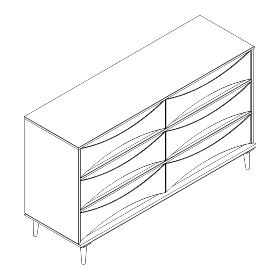
Item: BRATT6DRD-T
Please visit our website for the most current instructions, assembly tips, to report damage
or request parts. www.walkeredison.com
Copyright © 2018, by Walker Edison Furniture Co., LLC,
Copyright © 2018, by W
Assembly Instructions
alker Edison Furniture Co., LLC, All rights reserved.
Revised 10/2023-V1
All rights reserved.
P.1
Advertisement

Related Manuals for Walker Edison Grevilla BRATT6DRD-T


Summary of Contents for Walker Edison Grevilla BRATT6DRD-T
- Page 1 Please visit our website for the most current instructions, assembly tips, to report damage or request parts. www.walkeredison.com Revised 10/2023-V1 Copyright © 2018, by W Copyright © 2018, by Walker Edison Furniture Co., LLC, alker Edison Furniture Co., LLC, All rights reserved. All rights reserved.
- Page 2 A philips head screwdriver, hammer and tape measure is required for the assembly of this product.
-
Page 3: Parts List
Parts List Drawer Front 06 pcs Top panel 01 pc Left drawer side 06 pcs Left side panel 01 pc Right drawer side 05 pcs Right side panel 01 pc Drawer back 06 pcs Base 01 pc Drawer Bottom 06 pcs Front rail 02 pcs Large wood slider... -
Page 4: Hardware List
Hardware List Ø8*30mm Wooden dowel 58 pcs Wooden dowel Ø10*20mm 48 pcs 72 pcs Ø4,0*25mm Screw Ø3,5*30mm Screw 28 pcs Ø4,0*40mm Screw 09 pcs Ø10*10mm Nail 36 pcs Ø7,0*60mm Screw 01 pc Hex Key 01 pc Ø8*40mm Wooden dowel 12 pcs Cam bolt 33 pcs Cam lock... - Page 5 Step 1 Attention to the dowel size: ø10*20mm Insert wood dowel (B) into part 6 and 17. Ø10*20mm Step 2 Insert wood dowel (B) into part 9. Ø10*20mm Step 3 Insert wood dowel (A) into parts 2, 3, 5, 7, 11, 12, 15 and 16 Ø8*30mm...
- Page 6 1 - Ensure cam bolt is Step 4 installed straight and not at an angle. 2 - Tighten cam bolt until shoulder on cam bolt is flush. Do not over-tigh- ten. Fix the Cam bolt (J) in part 1 and 10 using a Philips head screwdriver.
- Page 7 Step 6 Rotate part 16. Secure part 17 to part 16 with screw (C) and Phillips head screwdriver. Ø4*25mm Step 7 Attach parts 5 to parts 2, 3 and 16, using screws (D) and Philips head screwdriver. Ø3,5*30mm...
- Page 8 Step 8 Secure foot 7 to base 4 using screw (C) and Philips head screwdriver. Ø4*25mm Step 9 Attach the center foot part 18 to base 4 using the screw (G) and the hex key (H). Ø7,0*60mm...
- Page 9 Step 10 Attach base 4 to body using screw (E) and Philips head screwdriver. Ø4*40mm Step 11 Align the opening in cam lock to the cam bolt and press into opening. Using a screwdriver, rotate the cam lock until it engages with the cam bolt and locks in place (anywhere between 90-180 degrees).
- Page 10 Step 12 17 17 17 17 Insert wood dowel (A) into parts 6 and 17. Ø8*30mm Step 13 Name and address of the supplier and date of production. Ø10*10mm Secure back panel 8 and hardware (Q) to body with nails (F) and hammer. P.10...
- Page 11 Step 14 Secure back panel 8 to body with nails (F) and hammer. Ø10*10mm Step 15 Attach part 9 to part 10, with screws (C) and Philips head screwdriver. Ø4*25mm P.11...
- Page 12 Step 16 Attach parts 11, 12 and 15 to part 10 with Cam lock (K) and Philips head screwdriver. Step 17 Insert part 14 between parts 11 and 12. Attach part 13 to parts 11 and 12 with Ø3,5*30mm screws(D), and Phillips head screwdriver. P.12...
- Page 13 Step 18 The assembled drawer with this warning must be placed on top of the unit. Insert wood dowel (I) on the inside of all drawers, with the drawer inside the unit after having passed the wood dowel that is in the drawer slide. The dowel is not flush with the panel, it is a little inside the drawer to help when you need to remove the lock dowel to remove the drawer.
- Page 14 Step 19 Attach part (L) with screw (O) and washer (M), in the frame of unit top panel using Phillips head screwdriver. With drilling machine make one hole in the wall, insert part (N) in the hole. Secure part (L) with screw (P) and washer (M) in the wall using a Phillips head screwdriver.
- Page 15 Step 20 Assembly Complete! P.15...
Need help?
Do you have a question about the Grevilla BRATT6DRD-T and is the answer not in the manual?
Questions and answers