
Related Manuals for Epever XTRA1206 G3


Summary of Contents for Epever XTRA1206 G3
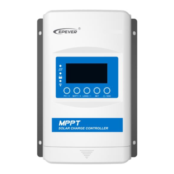
- Page 1 MPPT Solar Charge Controller User Manual Models: XTRA1206/1210/2206/2210/3210/3215/3415/4210/4215/4415N G3 XTRA1206/1210/2206/2210/3210/3215/3415/4210/4215/4415N G3 BLE...
- Page 2 Important Safety Instructions Please keep this manual for future review. This manual contains all safety, installation, and operation instructions for the XTRA-N G3 or XTRA-N G3 BLE series Maximum Power Point Tracking (MPPT) controller ("controller" as referred to in this manual). General Safety Information ...
- Page 3 Disclaimers The warranty does not apply to the following conditions: Damage caused by improper use or inappropriate environment (such as the humid, high salt spray, corrosion, greasy, flammable, explosive, dust accumulative, or other severe environments). The actual current/voltage/power exceeds the limit value of the controller. ...
-
Page 4: Table Of Contents
CONTENTS 1 General Information 1.1 Overview 1.2 Characteristics 1.3 Naming rules 1.4 Connection diagram 2 Installation 2.1 Attentions 2.2 PV array requirements 2.3 Wire size 2.4 Mounting 3 Display units 3.1 Indicator 3.2 Button 3.3 Display 3.4 Setting parameters 4 Parameters Setting 4.1 Battery parameters 4.1.1 Supported battery types 4.1.2 Local setting... - Page 5 4.2.2 RS485 communication setting 5 Others 5.1 Protection 5.2 Troubleshooting 5.3 Maintenance 6 Technical Specifications Annex I Conversion Efficiency Curves...
-
Page 6: General Information
1 General Information 1.1 Overview XTRA-N G3/XTRA-N G3 BLE series controllers, based on a new design concept, adopt the solar charge controller as the main component. A built-in Bluetooth module is a must for the XTRA-N G3 BLE series, which helps the end-users read and write parameters by phone APP conveniently. The controllers adopt the advanced MPPT control algorithm, improving the maximum power point (MPP) tracking and acting speed. - Page 7 Charging power reduction automatically for over-temperature ③ Built-in Bluetooth to adjust settings through EPEVER APP RS485 communication interface with optional 4G or Wi-Fi modules for remote monitoring Setting parameters via the PC software, APP, or remote meter ...
-
Page 8: Characteristics
3-protected against sprays to 60° from the vertical. ⑥ After disabling the COM port, the self-consumption is lower than 10mA. 1.2 Characteristics ❽ ❼ ❻ ❸ ❶ ❷ ❹ ❺ ★ ❶ ❺ port RS485 communication port ❷ ❻ PV terminals Terminal protection cover ❸... -
Page 9: Naming Rules
1.3 Naming rules Naming rules for products without Bluetooth module XTRA 1 2 10 N G3 G3: The 3 generation product N: Common negative system PV maximum open-circuit voltage: 06 means 60V; 10 means 100V; 15 means 150V Battery rated voltage: 2 means 12/24VDC; 4 means 12/24/36/48VDC Rated charging &... - Page 10 No-battery Mode When there is no battery, the XTRA-N G3/XTRA-N G3 BLE series can be directly connected to the inverter. The inverter shall be connected to the battery terminals of the controller and meets the following conditions: 1) For high-frequency inverter: PV input power > (load output power÷inverter WARNING conversion efficiency÷controller conversion efficiency) 2) For power frequency inverter: PV input power >...
-
Page 11: Installation
2 Installation 2.1 Attentions Please read the instructions to familiarize yourself with the installation steps before installation. Be very careful when installing the batteries, especially flooded lead-acid batteries. Please wear eye protection, and have fresh water available to wash and clean any contact with battery acid. - Page 12 XTRA1206/2206N G3/XTRA1206/2206N G3 BLE: 36 cell 48 cell 54 cell 60 cell System Voc<23V Voc<31V Voc<34V Voc<38V voltage Max. Best Max. Best Max. Best Max. Best 72 cell 96 cell Thin-Film System Voc<46V Voc<62V Module voltage Voc>80V Max. Best Max. Best NOTE: The above parameter values are calculated under standard test conditions (STC (Standard Test Condition): Irradiance 1000W/m...
-
Page 13: Wire Size
72 cell 96 cell Thin-Film System Voc<46V Voc<62V Module Voc voltage >80V Max. Best Max. Best NOTE: The above parameter values are calculated under standard test conditions (STC (Standard Test Condition): Irradiance 1000W/m , Module Temperature 25℃, Air Mass1.5.) XTRA3415/4415N G3/XTRA3415/4415N G3 BLE: 36 cell 48 cell 54 cell... - Page 14 * Max. PV wire size Model Max. PV input current XTRA1206/1210N G3 /12AWG XTRA1206/1210N G3 BLE XTRA2206/2210N G3 /10AWG XTRA2206/2210N G3 BLE XTRA3210/3215/3415N G3 10mm /8AWG XTRA3210/3215/3415N G3 BLE XTRA4210/4215/4415N G3 16mm /6AWG XTRA4210/4215/4415N G3 BLE * These are the maximum wire sizes that will fit the controller terminals. When the PV modules are connected in series, the open-circuit voltage of the PV array must not exceed 46V (XTRA**06N G3/ XTRA**06N G3 BLE), 92V CAUTION...
-
Page 15: Mounting
2.4 Mounting Risk of explosion! Never install the controller in a sealed enclose with flooded batteries! Do not install in a confined area where battery gas can accumulate. Risk of electric shock! When wiring the solar modules, the PV array can WARNING produce a high open-circuit voltage, so disconnect the breaker before wiring and be careful. - Page 16 Step 2:Connect the system in the order of ❶battery ❷load ❸PV array by Figure 2-2,” Schematic Wiring Diagram” and disconnect the system in the reverse order❸❷❶. Figure 2-2 Schematic of wiring diagram While wiring the controller, do not connect the circuit breaker or fast-acting fuse.
- Page 17 A common-negative controller for a common-negative system, such as the motorhome, is recommended. CAUTION The controller may be damaged if a common-positive controller is used and the positive electrode is grounded in the common-negative system. Step 4:Connect accessories Connect the remote temperature sensor cable Remote Temperature Sensor Temperature Sensor Cable (Optional)
-
Page 18: Display Units
3 Display units 3.1 Indicator Indicator Color Status Instruction PV charges the battery with a low current Green On Solid 1. No sunlight 2. Connection error Green 3. Low PV voltage Normal charging Green Slowly Flashing(1Hz) Green Fast Flashing(4Hz) PV Over voltage Green On Solid Normal... -
Page 19: Button
3.2 Button PV browsing interface Press the button Setting data + Setting the LCD cycle time, enabling or disabling the Press the button and hold 5s COM port BATT browsing interface Press the button Cursor displacement during setting Setting the battery type, battery capacity level, and Press the button and hold 5s temperature unit. -
Page 20: Setting Parameters
Display:Voltage/Current/Power/Generated Energy 2) Battery parameters Display:Voltage/Current/Temperature/Battery capacity level 3) Load parameters Display:Voltage/Current/Power/ Consumed energy/Load working mode-Timer1/ Load working mode-Timer2 3.4 Setting parameters 1) Battery type... - Page 21 Note: If the controller supports 48V system voltage, the battery type will display LiFePO4 F15/F16 and Li(NiCoMn)O2 N13/N14. Operation: Step 1: Press the button to browse the battery parameters on the initial interface. Then, press button to enter the battery parameters setting interface. Step 2: Long-press the button to enter the battery-type interface.
- Page 22 Step 1: Press the button to browse the battery parameters on the initial interface. Then, press button to enter the battery parameters setting interface. Step 2: Long-press the button to enter the battery-type interface. Step 3: Press the button twice to jump to the temperature unit's interface. Step 4: Press the button to set the temperature units.
- Page 23 The RS485 com port supports 5V output and communication function when enabled. And it has no output and communication function when disabled. At the same time, the system's self- consumption is reduced further. Operation: Step 1: Press the button to browse the PV parameters on the initial interface. Then, press button to enter the PV parameters setting interface.
-
Page 24: Parameters Setting
4 Parameters Setting 4.1 Battery parameters 4.1.1 Supported battery types Sealed(default) Battery Flooded Lithium LiFePO4 (4S/8S/15S/16S) battery Li(NiCoMn)O2 (3S/6S/7S/13S/14S) User Note: If the controller supports 48V system voltage, the battery type will display LiFePO4 F15/F16 and Li(NiCoMn)O2 N13/N14. 4.1.2 Local setting When the default battery type is selected, the battery voltage parameters cannot be modified. - Page 25 button to select the battery type “USE.” 4) Press the Step2: Set the battery parameters on the local device. Under the "USE" interface, the battery parameters that can be local set are shown in the table below: Parameters Default Range Operation steps 1) Under the "USE"...
-
Page 26: Remote Setting
For the no-battery application, if the actual system voltage is 12V, the SYS value can be set as “12VDC” or “0 (auto identify the system voltage)”. If the actual system voltage is higher than 12V, such as 24V/36V/48V, the SYS value must be the same as the actual system voltage. - Page 27 Setting the battery parameters by APP Via an external WiFi module Connect the controller to an external WiFi module by the RS485 communication port. End-users can set the voltage parameters by the APP after selecting the battery type as "USE." Refer to the cloud APP manual for details.
- Page 28 Setting the battery parameters by MT52 Connect the controller to the remote meter (MT52) through a standard network cable. After selecting the battery type as "USE," set the voltage parameters by the MT52. Refer to the MT52 manual or aftersales engineer for details. Controller parameters ...
- Page 29 Under voltage warning 9~15.5V 12.0V 12.0V 12.0V voltage Low voltage disconnect 9~15.5V 11.1V 11.1V 11.1V voltage Discharging limit voltage 10.6V 10.6V 10.6V 9~15.5V 0~180 Equalize Duration 120 minutes 120 minutes minutes 10~180 Boost Duration 120 minutes 120 minutes 120 minutes minutes ...
- Page 30 Under voltage warning reconnect 12.2 V 24.4 V 45.7V 48.8V 9~15.5V voltage Under voltage 12.0 V 24.0 V 45.0V 48.0V 9~15.5V warning voltage Low voltage 11.1 V 22.2 V 41.6V 44.4V 9~15.5V disconnect voltage Discharging limit 11.0 V 22.0 V 41.2V 44.0V 9~15.5V...
-
Page 31: Load Modes
① The battery parameters under the “User” battery type are 9~17V for LFP4S. They should be x2 for LFP8S and x4 for LFP15S/LFP16S. When the battery type is "USE," the Lithium battery voltage parameters follow the following logic: A. Over Voltage Disconnect Voltage>Over Charging Protection Voltage(Protection Circuit Modules(BMS))+0.2V;... - Page 32 Load mode Timer 1 Timer 2 Light ON/OFF Disabled The load will be on for 1 hour after The load will be on for 1 hour sunset before sunrise The load will be on for 2 hours after The load will be on for 2 hours sunset before sunrise The load will be on for 3~13 hours...
- Page 33 Light ON+ Timer Time Control Control the load ON/OFF time by setting the real-time clock. 2) Load mode settings Set the load modes by PC software, APP, or remote meter (MT52). For detailed connection diagrams and settings, refer to chapter 4.1.3 Remote Setting.
- Page 34 5 Others 5.1 Protection Protections Instructions When the charging current or power of the PV array exceeds the controller’s rated current or power, it will be charged at the rated current or power. PV over current/ over WARNING: When the PV’s charging current is higher than the rated current, the PV’s open-circuit voltage cannot power be higher than the "maximum PV open-circuit voltage."...
- Page 35 When the battery voltage reaches the low voltage disconnect voltage, it will automatically stop battery discharging to prevent Battery over discharge battery damage caused by over-discharging. (Any connected loads will be disconnected. Loads directly connected to the battery will not be affected and may continue to discharge the battery.) The controller can detect the battery temperature through an external temperature sensor.
- Page 36 For example XTRA4215N G3/XTRA4215N G3 BLE 24V system: 5.2 Troubleshooting Possible Faults Troubleshooting reasons Charging LED indicator off during PV array Confirm that PV wire connections are daytime when sunshine falls on PV disconnection correct and tight modules properly. Battery voltage The wire connection is correct, and Please check the battery voltage.
- Page 37 When the heat sink of the controller exceeds 85℃, the controller will Controller automatically cut off the input and Overheating output circuit. When the temperature is below 75℃, the controller will resume work. ①Check whether the battery voltage matches the system voltage level PV and BATT indicators fast flash.
- Page 38 5.3 Maintenance The following inspections and maintenance tasks are recommended at least twice yearly for best performance. Make sure the controller is firmly installed in a clean and dry ambient. Make sure no block on airflow around the controller. Clear up any dirt and fragments on the heat sink.
- Page 39 6 Technical Specifications XTRA1206N XTRA2206N XTRA1210N XTRA2210N XTRA3210N XTRA4210N Item G3/G3 BLE G3/G3 BLE G3/G3 BLE G3/G3 BLE G3/G3 BLE G3/G3 BLE Electrical Parameters Battery Rated 12/24VDC★ Auto Voltage Rated Charging Current Rated Discharging Current Controller 8~32V Work Voltage Range PV Maximum 60V(At minimum operating environment 100V(At minimum operating environment temperature)
- Page 40 Maximum 97.9% 98.3% 98.2% 98.3% 98.6% 98.6% Conversion Efficiency Maximum 96.7% 96.2% 96.4% 96.6% 96.5% Load Efficiency Static Losses ≤10mA(12V) ≤10mA(12V) ≤15mA(12V) ≤15mA(12V) ≤15mA(12V) ≤15mA(12V) (Enable ≤7mA(24V) ≤7mA(24V) ≤9mA(24V) ≤9mA(24V) ≤9mA(24V) ≤9mA(24V) com. port) Static Losses ≤8mA(12V) ≤8mA(12V) ≤8mA(12V) ≤8mA(12V) ≤8mA(12V) ≤8mA(12V) (Disable...
- Page 41 Mounting Size 120×134mm 160×149mm 120×134mm 160×149mm 173×156mm 200×176mm (L x W) Mounting Hole Φ5mm Φ5mm Φ5mm Φ5mm Φ5mm Φ5mm Size 12AWG(4mm 6AWG(16mm 12AWG(4mm 6AWG(16mm 6AWG(16mm 6AWG(16mm Terminal Recommended 12AWG(4mm 10AWG(6mm 12AWG(4mm 10AWG(6mm 8AWG(10mm 6AWG(16mm Wire Size 0.58kg 0.97kg 0.59kg 0.97kg 1.30kg 1.72kg Net Weight...
- Page 42 390W/12V 520W/12V Rated Charging 390W/12V 520W/12V 780W/24V 1040W/24V 780W/24V 1040W/24V 1170W/36V 1560W/36V Power 1560W/48V 2080W/48V Maximum 97.6% 97.9% 98.1% 98.5% Conversion Efficiency Maximum Load 95.1% 95.4% 96.9% 97.2% Efficiency ≤14mA(12V) ≤14mA(12V) Static Losses ≤15mA(12V) ≤15mA(12V) ≤9mA(24V) ≤9mA(24V) (Enable com. ≤9mA(24V) ≤9mA(24V) ≤8mA(36V) ≤8mA(36V)
- Page 43 (L x W) Φ5mm Φ5mm Φ5mm Φ5mm Mounting Hole Size 6AWG(16mm 6AWG(16mm 6AWG(16mm 6AWG(16mm Terminal Recommended Wire 8AWG(10mm 6AWG(16mm 8AWG(10mm 6AWG(16mm Size 1.66kg 2.08kg 2.16kg 2.60kg Net Weight ★ When a lithium battery is used, the system voltage can’t be identified automatically. ◆...
- Page 44 Annex I Conversion Efficiency Curves Illumination Intensity: 1000W/m Temperature: 25º C Model: XTRA1206N G3/XTRA1206N G3 BLE Solar Module MPP Voltage(17V, 34V) / Nominal System Voltage(13V) MPPT: 17V 13V Conversion Efficiency Curves MPPT: 34V 98.00% 97.00% 96.00% 95.00% 94.00% 93.00% 92.00% 91.00% 90.00% 89.00%...
- Page 45 Model: XTRA1210N G3/XTRA1210N G3 BLE Solar Module MPP Voltage(17V, 34V) / Nominal System Voltage(13V) MPPT: 17V 13V Conversion Efficiency Curves MPPT: 34V 98.00% 97.00% 96.00% 95.00% 94.00% 93.00% 92.00% 91.00% 90.00% 89.00% 88.00% Rated Power W Solar Module MPP Voltage(34V, 51V, 68V) / Nominal System Voltage(26V) MPPT: 34V 26V Conversion Efficiency Curves MPPT: 68V...
- Page 46 Model: XTRA2206N G3/XTRA2206N G3 BLE Solar Module MPP Voltage(17V, 34V) / Nominal System Voltage(13V) MPPT: 17V 13V Conversion Efficiency Curves MPPT: 34V 98.00% 97.00% 96.00% 95.00% 94.00% 93.00% 92.00% 91.00% 90.00% 89.00% 88.00% Rated Power W Solar Module MPP Voltage(34V, 42V) / Nominal System Voltage(26V) MPPT: 34V 26V Conversion Efficiency Curves MPPT: 42V...
- Page 47 Model: XTRA2210N G3/XTRA2210N G3 BLE Solar Module MPP Voltage(17V, 34V) / Nominal System Voltage(13V) MPPT: 17V 13V Conversion Efficiency Curves MPPT: 34V 98.00% 97.00% 96.00% 95.00% 94.00% 93.00% 92.00% 91.00% 90.00% 89.00% 88.00% Rated Power W Solar Module MPP Voltage(34V, 51V, 68V) / Nominal System Voltage(26V) MPPT: 34V 26V Conversion Efficiency Curves MPPT: 68V...
- Page 48 Model: XTRA3210N G3/XTRA3210N G3 BLE Solar Module MPP Voltage(17V, 34V) / Nominal System Voltage(13V) MPPT: 17V 13V Conversion Efficiency Curves MPPT: 34V 98.00% 97.00% 96.00% 95.00% 94.00% 93.00% 92.00% 91.00% 90.00% 89.00% 88.00% Rated Power W Solar Module MPP Voltage(34V, 51V, 68V) / Nominal System Voltage(26V) MPPT: 34V MPPT: 68V 26V Conversion Efficiency Curves...
- Page 49 Model: XTRA4210N G3/XTRA4210N G3 BLE Solar Module MPP Voltage(17V, 34V) / Nominal System Voltage(13V) MPPT: 17V 13V Conversion Efficiency Curves MPPT: 34V 98.00% 97.00% 96.00% 95.00% 94.00% 93.00% 92.00% 91.00% 90.00% 89.00% 88.00% Rated Power W Solar Module MPP Voltage(34V, 51V, 68V) / Nominal System Voltage(26V) MPPT: 34V MPPT: 68V 26V Conversion Efficiency Curves...
- Page 50 Model: XTRA3215N G3/XTRA3215N G3 BLE Solar Module MPP Voltage(17V, 34V, 68V) / Nominal System Voltage(13V) MPPT: 17V 13V Conversion Efficiency Curves MPPT: 34V MPPT: 68V 98.00% 97.00% 96.00% 95.00% 94.00% 93.00% 92.00% 91.00% 90.00% 89.00% 88.00% Rated Power W Solar Module MPP Voltage(34V, 68V, 102V) / Nominal System Voltage(26V) MPPT: 34V MPPT: 102V 26V Conversion Efficiency Curves...
- Page 51 Model: XTRA4215N G3/XTRA4215N G3 BLE Solar Module MPP Voltage(17V, 34V, 68V) / Nominal System Voltage(13V) MPPT: 17V 13V Conversion Efficiency Curves MPPT: 34V MPPT: 68V 98.00% 97.00% 96.00% 95.00% 94.00% 93.00% 92.00% 91.00% 90.00% 89.00% 88.00% Rated Power W Solar Module MPP Voltage(34V, 68V, 102V) / Nominal System Voltage(26V) MPPT: 34V MPPT: 102V 26V Conversion Efficiency Curves...
- Page 52 Model: XTRA3415N G3/XTRA3415N G3 BLE Solar Module MPP Voltage(17V, 34V, 68V) / Nominal System Voltage(13V) MPPT: 17V MPPT: 34V 13V Conversion Efficiency Curves MPPT: 68V 98.00% 97.00% 96.00% 95.00% 94.00% 93.00% 92.00% 91.00% 90.00% 89.00% 88.00% 87.00% 86.00% Rated Power W Solar Module MPP Voltage(34V, 68V, 102V) / Nominal System Voltage(26V) MPPT: 34V 26V Conversion Efficiency Curves...
- Page 53 Solar Module MPP Voltage(65V, 102V, 115V) / Nominal System Voltage(39V) MPPT: 65V 39V Conversion Efficiency Curves MPPT: 115V MPPT: 102V 98.00% 97.00% 96.00% 95.00% 94.00% 93.00% 92.00% 91.00% 90.00% 89.00% 88.00% 1000 1200 1400 Rated Power W Solar Module MPP Voltage(68V, 102V, 119V) / Nominal System Voltage(52V) MPPT: 68V 52V Conversion Efficiency Curves MPPT: 119V...
- Page 54 Model: XTRA4415N G3/XTRA4415N G3 BLE Solar Module MPP Voltage(17V, 34V, 68V) / Nominal System Voltage(13V) MPPT: 17V MPPT: 34V 13V Conversion Efficiency Curves MPPT: 68V 98.00% 97.00% 96.00% 95.00% 94.00% 93.00% 92.00% 91.00% 90.00% 89.00% 88.00% Rated Power W Solar Module MPP Voltage(34V, 68V, 102V) / Nominal System Voltage(26V) MPPT: 34V MPPT: 102V 26V Conversion Efficiency Curves...
- Page 55 Solar Module MPP Voltage(68V, 102V, 119V) / Nominal System Voltage(39V) MPPT: 68V MPPT: 119V 39V Conversion Efficiency Curves MPPT: 102V 98.00% 97.00% 96.00% 95.00% 94.00% 93.00% 92.00% 91.00% 90.00% 89.00% 88.00% 800 1000 1200 1400 1600 1800 Rated Power W Solar Module MPP Voltage(68V, 102V, 119V) / Nominal System Voltage(52V) MPPT: 68V MPPT: 119V...
- Page 56 HUIZHOU EPEVER TECHNOLOGY CO., LTD. Tel: +86-752-3889706 E-mail: info@epever.com Website: www.epever.com...
Need help?
Do you have a question about the XTRA1206 G3 and is the answer not in the manual?
Questions and answers