Table of Contents
Advertisement
Quick Links
A S S E M B L Y M A N U A L
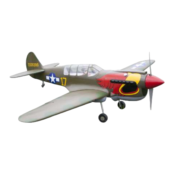
Curtiss P-40N Warhawk
Code: SEA250
" Graphics and speciications may change without notice ".
( SEA250P)
Speciications:
Wingspan---------------80 in ( 203.2 cm).
Wing area---------------1094.3 sq.in ( 70.6 sq.dm).
Weight-------------------19.8-21.2 lbs ( 9.0-9.6 kg).
Length-------------------63.6 in ( 161.5 cm).
Engine-------------------38-61cc
Motor size---------------Power 360
(SEA250S)
Radio--------------------8 channels with 8 servos.
Electric Power Conversion Optional.
1
Advertisement
Table of Contents

Related Manuals for SG Models Curtiss P-40N Warhawk


Summary of Contents for SG Models Curtiss P-40N Warhawk
- Page 1 A S S E M B L Y M A N U A L Curtiss P-40N Warhawk Code: SEA250 “ Graphics and speciications may change without notice ”. ( SEA250P) Speciications: Wingspan---------------80 in ( 203.2 cm). Wing area---------------1094.3 sq.in ( 70.6 sq.dm).
-
Page 2: Kit Contents
Instruction Manual. INTRODUCTION. hank you for choosing the CURTISS P-40N WARHAWK ARF by SG MODELS. he CUR- TISS P-40N WARHAWK was designed with the intermediate/advanced sport lyer in mind. It is a semi scale airplane which is easy to ly and quick to assemble. he airframe is conven- tionally built using balsa, plywood to make it stronger than the average ARF, yet the design allows the aeroplane to be kept light. -
Page 3: Additional Items Required
HINGING THE FLAP. KIT CONTENTS. SEA25001 Fuselage SEA25002 Wing set SEA25003 Tail set SEA25004 Canopy SEA25005 Cowling SEA25006 Aluminium tube SEA25007 Pilot ADDITIONAL ITEMS REQUIRED. � 33cc-38cc gasoline engine. � Power 160 � Computer radio with 10 servos. � Glow plug to suit engine. �... -
Page 4: Hinging The Aileron
Curtiss P-40N Warhawk Instruction Manual. Hinge. 3) Slide the wing panel on the aileron until there is only a slight gap. he hinge is now centered on the wing panel and aileron. Re- move the T-pins and snug the aileron against the wing panel. - Page 5 5) Turn the wing panel over and delect the aileron in the opposite direction from the opposite side. Apply thin C/A glue to each hinge, making sure that the C/A penetrates into both the aileron and wing panel. Epoxy. 6) Using C/A remover/debonder and a pa- per towel, remove any excess C/A glue that may have accumulated on the wing or in the aileron hinge area.
-
Page 6: Wing Assembly
Curtiss P-40N Warhawk Instruction Manual. Epoxy. WING ASSEMBLY. Please see below pictures. INSTALLING THE AILERON SERVOS. Epoxy. Attach the aluminum tube into wing. Servos Mininum servo spec. Torque : 110 oz-in (7.9 kg-cm) @ 4.8V; 131 oz-in (9.4 kg-cm) @ 6.0V... - Page 7 5) Use dental loss to secure the connec- Because the size of servos difer, you tion so they cannot become unplugged. may need to adjust the size of the precut opening in the mount. he notch in the sides of the mount allow the servo lead to pass through.
-
Page 8: Aileron Pushrod Installation
Curtiss P-40N Warhawk Instruction Manual. INSTALLING THE FLAP SERVO. Repeat the procedure for the lap servo. AILERON PUSHROD INSTALLATION. Please see below pictures. 9) Set the aileron hatch in place and use a Phillips screw driver to install it with four wood screws. - Page 9 M3 lock nut. SERVO ROTATING RETRACT M3 clevis. LANDING GEAR. Please see below pictures. INSTALLING THE FLAP PUSHROD. Repeat the procedure for the aileron pushrod. 40mm. M3 lock nut. M3 clevis.
- Page 10 Curtiss P-40N Warhawk Instruction Manual. head locker glue. 3x20mm.
- Page 11 Epoxy. 2x6mm. Epoxy.
-
Page 12: Installing The Fuselage Servos
Curtiss P-40N Warhawk Instruction Manual. INSTALLING THE FUSELAGE SERVOS. Because the size of servos difer, you may need to adjust the size of the precut opening in the mount. he notch in the sides of the mount allow the servo lead to pass through. -
Page 13: Installing The Stopper Assembly
Loctite secure. Adjustable servo connector. Servo arm. Switch. hrottle servo arm. INSTALLING THE ENGINE SWITCH. INSTALLING THE RECEIVER SWITCH. Trim and cut. Install the switch into the precut hole in the side, in the fuselage. 3/32” Hole. Switch. INSTALLING THE STOPPER ASSEMBLY. -
Page 14: Fuel Tank Installation
Curtiss P-40N Warhawk Instruction Manual. 2) Using a modeling knife, cut one length 6) When satisied with the alignment of the of silicon fuel line. Connect one end of stopper assembly tighten the 3 x 20mm ma- the line to the weighted fuel pick up and chine screw until the rubber stopper expands and seals the tank opening. -
Page 15: Mounting The Engine
7) Slide the fuel tank into the fuselage. Guide the lines from the tank through the hole in the irewall. Vent tube. Fuel ill tube. Fuel pick up tube. 9) Connect the lines from the tank to the en- gine and muler. he vent line will connect to the muler and the line from the clunk to the carburetor. - Page 16 Curtiss P-40N Warhawk Instruction Manual. 7mm. Locate the engine mounting in position on the irewall. Use a 2.5mm drill bit to drill the holes necessary to mount your particular motor choice. 5x80mm. 2.5mm.
- Page 17 170mm.
- Page 18 Curtiss P-40N Warhawk Instruction Manual. Move the throttle stick to the closed po- sition and move the carburetor to closed. Use a 2.5mm hex wrench to tighten the screw that secures the throttle pushrod wire. Make sure to use threadlock on the screw so it does not vibrate loose.
- Page 19 Cut. Tape the cowl to the fuselage using low- Install the muler and muler extension tack tape. onto the engine and make the cutout in the cowl for muler clearance. Connect the fuel and pressure lines to the carbu- retor, muler and fuel iler valve. Secure the cowl to fuselage using the M3x10mm socket head screws.Putting a small length of silicon fuel tube under the head of the...
- Page 20 Curtiss P-40N Warhawk Instruction Manual. ELECTRIC POWER CONVERSION Locate the items neccessary to install the electric power conversion included with your model. Recommend the items necessary to install the electric power conversion parts included with your model. - Motor: 360 - 6000 Watts...
- Page 21 hen, use 5mm drill bit to enlarge the Attach the motor mount to the front of the holes on the electric motor box. electric motor box using four 5mm blind nut, four M5x30mm hex head bolts to se- cure the motor. Please see picture shown. 5mm.
- Page 22 Curtiss P-40N Warhawk Instruction Manual. 170mm Battery. Epoxy. Attach the speed control to the side of the motor box using two-sided tape and tie wraps. Connect the appropriate leads from the speed control to the mo- tor. Make sure the leads will not interfere with the operation of the motor.
-
Page 23: Hinging The Elevator
HINGING THE ELEVATOR. Glue the elevator hinges in place using the same techniques used to hing the ailerons. M4 Nylon. INSTALLING THE SPINNER. INSTALL ELEVATOR CONTROL HORN. Fiberglass control horn he propeller should not touch any part of the spinner cone. If it does, use a sharp modeling knife and carefully trim away the spinner cone where the propel- ler comes in contact with it. - Page 24 Curtiss P-40N Warhawk Instruction Manual. Epoxy. Fiberglass control horn Elevator iberglass control horn. Use knife to remove covering Epoxy. Rudder iberglass control horn. INSTALL RUDDER HINGE. Glue the rudder hinges in place using the same techniques used to hinge the el- evator.
-
Page 25: Installing Horizontal Stabilizer
INSTALLING HORIZONTAL STABILIZER. RUDDER PUSHROD INSTALLATION. 1) Locate items necessary to install rud- der pushrod. Rudder control horn. hread one clevis and M3 lock nut on to each elevator control rod. hread the horns on until they are lush with the ends of the control rods. -
Page 26: Elevator Pushrod Installation
Curtiss P-40N Warhawk Instruction Manual. Assemble the elevator and rudder pushrods as shown in images below. 775mm. Ball Link. Elevator pushrod. M3 clevis. Rudder pushrod. ELEVATOR PUSHROD INSTALLATION. Hex nut. Fuel tubing. 1) Locate items necessary to install eleva- tor pushrod. -
Page 27: Mounting The Tail Wheel
MOUNTING THE TAIL WHEEL. 545mm. M3 clevis M3 lock nut. Epoxy. - Page 28 2) A scale pilot is included with this ARF. he Pilot included itting well to the cockpit. (or you can order others scale pilot igures made by SG Models. hey are available at SG Models distributors.) If you are going to install a pilot igure, please use a sanding bar to sand the base of the igure so that it is lat.
-
Page 29: Apply The Decals
Epoxy. APPLY THE DECALS. 1) If all the decals are precut and ready to stick. Please be certain the model is clean and free from oily ingerprints and dust. Position decal on the model where de- sired, using the photos on the box and aid in their location. - Page 30 Curtiss P-40N Warhawk Instruction Manual. ATTACHMENT WING- FUSELAGE.
- Page 31 Insert wing gun onto the wings.
-
Page 32: Control Throws
Curtiss P-40N Warhawk Instruction Manual. With the wing attached to the fuselage, all parts of the model installed ( ready to ly), and empty fuel tanks, hold the mod- el at the marked balance point with the stabilizer level. Lit the model. If the tail drops when you lit, the model is “tail heavy”... -
Page 34: Flight Preparation
An out of balance propeller will cause If it does not, lip the servo reversing excessive vibration which could lead switch on your transmitter to change to engine and/or airframe failure. the direction. We wish you many safe and enjoyable lights with your CURTISS P-40N WARHAWK.
Need help?
Do you have a question about the Curtiss P-40N Warhawk and is the answer not in the manual?
Questions and answers