Table of Contents
Advertisement
Quick Links
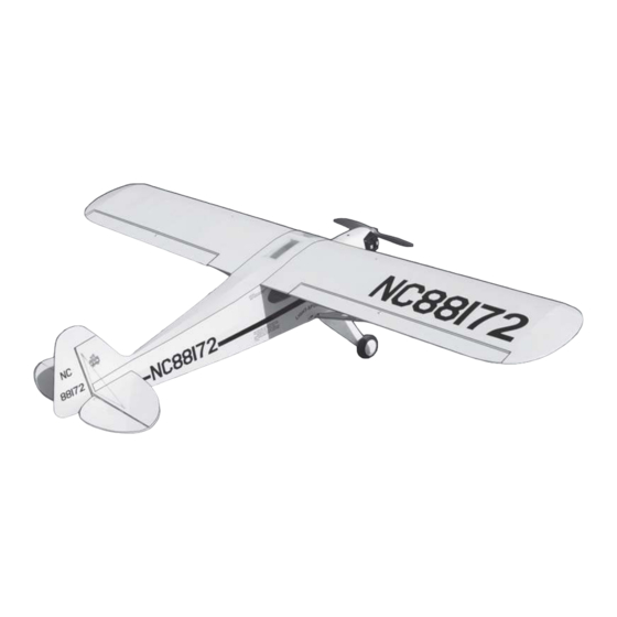
"Graphics and specifications may change without notice".
Specifications
Wingspan---------------------------------------- 88.2 in---------------------------- 224cm.
Wing area--------------------------------------- 1137.1 sq.in--------------- 73.4 sq.dm.
Approximate flying weight--------------------9.95- 11 lbs------------------4.5 - 5kg.
Length--------------------------------------------- 56.2in-------------------------- 142.7cm.
Recommended engine size---------------- 20-26cc.
-----------------------------------------------------1.2-1.5 4-stroke engine.
Radio System required 4 channels with 6 servos
Flying skill level Intermediate/advanced.
•
Ready-made—minimal assembly & finishing required.
•
Ready-covered covering.
•
Photo-illustrated step-by-step Assembly Manual.
Made in Vietnam.
ASSEM BLY M AN UAL
K it fe a t ure s.
MS: 74
Advertisement
Table of Contents

Related Manuals for SG Models PIPER CUB


Summary of Contents for SG Models PIPER CUB
- Page 1 MS: 74 ASSEM BLY M AN UAL “Graphics and specifications may change without notice”. Specifications Wingspan---------------------------------------- 88.2 in---------------------------- 224cm. Wing area--------------------------------------- 1137.1 sq.in--------------- 73.4 sq.dm. Approximate flying weight--------------------9.95- 11 lbs------------------4.5 - 5kg. Length--------------------------------------------- 56.2in-------------------------- 142.7cm. Recommended engine size---------------- 20-26cc. -----------------------------------------------------1.2-1.5 4-stroke engine. Radio System required 4 channels with 6 servos Flying skill level Intermediate/advanced.
- Page 2 CODE SEA 74. INTRODUCTION. Thank you for choosing the PIPER CUB ARTF by SG MODELS. The PIPER CUB was designed with the intermediate/advanced sport scale in mind. It is a semi scale airplane which is easy to fly and quick to assemble. The airframe is conventionally built using balsa, plywood to make it stronger than the average ARTF , yet the design allows the aeroplane to be kept light.
-
Page 3: Hinging The Ailerons
This will ensure proper Hinge. assembly as the PIPER CUB is made from natural materials and minor adjustments may have to be made. The paint and plastic parts 3) Slide the wing panel on the aileron until used in this kit are fuel proof. -
Page 4: Hinging The Elevator
Instruction Manual PIPER CUB_ CODE SEA 74. 5) Turn the wing panel over and deflect the aileron in the opposite direction from the opposite side. Apply thin C/A glue to each hinge, making sure that the C/A penetrates into both the aileron and wing panel. 6) Using C/A remover/debonder and a paper towel, remove any excess C/A glue that may have accumulated on the wing or in the... -
Page 5: Rudder Control Horn
Wing. Aileron. Elevator control horn. RUDDER CONTROL HORN. Rudder control horn: ELEVATOR CONTROL HORN. Using the same techniques used aileron control horn. See picture below. Install the elevator control horn using the same method as with the aileron control horns. 2 sets. -
Page 6: Installing The Stopper Assembly
Instruction Manual PIPER CUB_ CODE SEA 74. INSTALLING THE STOPPER ASSEMBLY. 1) Using a modeling knife, carefully cut off the rear portion of one of the 3 nylon tubes leaving 1/2” protruding from the rear of the stopper. This will be the fuel pick up tube. Rudder control horn. -
Page 7: Landing Gear Installation
Vent tube. Fuel pick up tube. Rubber band. Fuel fill tube. Fuel tank. Carefully use a lighter or heat gun to permenently set the angle of the vent tube. Important: When the stopper assembly is in- stalled in the tank, the top of the vent tube should rest just below the top surface of the Vent tube. - Page 8 Instruction Manual PIPER CUB_ CODE SEA 74. 3 x15mm. 3 x12mm. 3 x15mm.
- Page 9 3 x12mm. 1/4 inch (6mm)
- Page 10 Instruction Manual PIPER CUB_ CODE SEA 74.
-
Page 11: Mounting The Engine
5) Bolt the engine to the engine mount using MOUNTING THE ENGINE. the four machine screws. Double check that all the screws are tight before proceeding. 1) Install the pushrod housing through the 6) Attach the Z-Bend in the pushrod wire to predrilled hole in the firewall and into the servo the throttle arm on the carburetor. - Page 12 Instruction Manual PIPER CUB_ CODE SEA 74. 3) Install the muffler and muffler extension onto the engine and make the cut out in the cowl for muffler clearance. Connect the fuel and pressure lines to the carburetor, muffler and fuel filler valve. Secure the cowl to fuse- lage using the 3x10mm screws (4).
- Page 13 ELECTRIC POWER CONVERSION. 1) Locate the items neccessary to install the electric power conversion included with your model. M4x20mm and washers. 4) Attach the motor to the front of the electric motor box using four 4mm blind nut, four M4x20mm hex head bolts to se- cure the motor.
- Page 14 Instruction Manual PIPER CUB_ CODE SEA 74. 5) Attach the speed control to the side of the motor box using two-sided tape and tie wraps. Connect the appropriate leads from the speed control to the mo- tor. Make sure the leads will not interfere with the operation of the motor.
-
Page 15: Installing The Spinner
INSTALLING THE SPINNER. Install the spinner backplate, propeller and spinner cone. he propeller should not touch any part of the spinner cone. If it does, use a sharp modeling knife and carefully trim away the spinner cone where the propel- ler comes in contact with it. -
Page 16: Installing The Switch
Instruction Manual PIPER CUB_ CODE SEA 74. THROTTLE SERVO ARM INSTALLATION. INSTALLING THE SWITCH. Install adjustable servo connector in the servo Install the switch into the precut hole in the arm . side of fuselage. Loctite secure. Adjustable Servo connector. Servo arm. -
Page 17: Installing The Vertical Stabilizer
pen. When cutting through the covering to re- move it, cut with only enough pressure to only cut through the covering itself. Cutting into the balsa structure may weaken it. Pen. Remove covering. When cutting through the covering to re- move it, cut with only enough pressure to only cut through the covering itself. -
Page 18: Installing The Aileron Servos
Instruction Manual PIPER CUB_ CODE SEA 74. Put the vertical stabilizer into the in the top of the horizontal fin. The bottom edge of the stabilizer should also be firmly pushed against the top of the horizontal stabilizer. Epoxy. Vertical Stabilizer. - Page 19 INSTALLATION THE PUSHROD. Wing. Aileron. 75mm. M2 clevis. M2 lock nut. 110mm. Aileron. Aileron. ELEVATOR - RUDDER PUSHROD INSTALLATION. Wing. Rudder control horn. M2 lock nut. Aileron. Elevator control horn. Repeat the procedure for the other wing.
- Page 20 Instruction Manual PIPER CUB_ CODE SEA 74. Elevator and rudder pushrods assembly follow pictures below. M2 clevis. M2 Lock nut. Attach to elevator - rudder control horn. Attach to servo arm in fuselage. Throttle. Elevator. Rudder.
- Page 21 INSTALLING TAIL STRUT SUPPORT Control horn. The tail strut system assembly follow pic- Elevator Pushrod. tures below. M2 lock nut. Metal clevis. Elevator pushrod. 3x10mm. 3x15mm. Rudder pushrod. Elevator. Throttle. Rudder. Elevator. Vertical Fin. Horizontal Fin.
- Page 22 Instruction Manual PIPER CUB_ CODE SEA 74. Vertical Fin. Horizontal Fin. Fuselage bottom. Bottom. Vertical Fin. 3x10mm. Horizontal Fin. M3 x 10mm.
-
Page 23: Mounting The Tail Wheel
M3 x 10mm. MOUNTING THE TAIL WHEEL. See picture below. 3x25mm. 3 x10 mm. - Page 24 Instruction Manual PIPER CUB_ CODE SEA 74. 3x25 mm. 120MM. Aluminum tail Landing gear. INSTALLING THE BATTERY-RECEIVER. 3x10 mm. 1) Plug the six servo leads and the switch lead into the receiver. Plug the battery pack lead into the switch also. 2) Wrap the receiver and battery pack in the protective foam rubber to protect them from vibration.
-
Page 25: Installing The Wing Strut
INSTALLING THE WING STRUT. Parts requirement.See pictures below. 3x12mm. 3x12mm. - Page 26 Instruction Manual PIPER CUB_ CODE SEA 74. 3x15mm. 3x12mm. 3x15mm.
- Page 27 ATTACHMENT WING-FUSELAGE. Attach the aluminium tube into fuselage. Aluminum tube. 3x50mm. Wing tube. C/A glue. Insert two wing panels as pictures below.
- Page 28 Instruction Manual PIPER CUB_ CODE SEA 74. Wing bolt. Plastic Screw. BALANCING. 1) It is critical that your airplane be bal- anced correctly. Improper balance will cause your plane to lose control and crash. The cen- 9.5cm ter of gravity is locate back from the leading edge of the wing, measured at wing tip.
-
Page 29: Control Throws
95mm. CONTROL THROWS. 1) We highly recommend setting up the PIPER CUB using the control throws listed at right. We have listed control throws for both Low Rate (initial test flying/sport flying) and High Rate (aerobatic flying). 2) Turn on the radio system, and with the... - Page 30 Instruction Manual PIPER CUB_ CODE SEA 74. INITIAL FLYING AEROBATIC FLYING 4) By moving the position of the adjust- able control horn out from the control surface, you will decrease the amount of throw of that control surface. Moving the adjustable con- trol horn toward the control surface will in- crease the amount of throw.
-
Page 31: Flight Preparation
2) Check every bolt and every glue joint B) Plug in your radio system per the in the PIPER CUB to ensure that everything manufacture’s instructions and turn every thing is tight and well bonded. 3) Double check the balance of the air- C) Check the elevator first.
Need help?
Do you have a question about the PIPER CUB and is the answer not in the manual?
Questions and answers