Table of Contents
Advertisement
Quick Links
A S S E M B L Y M A N U A L
Code: SEA257
" Graphics and speciications may change without notice ".
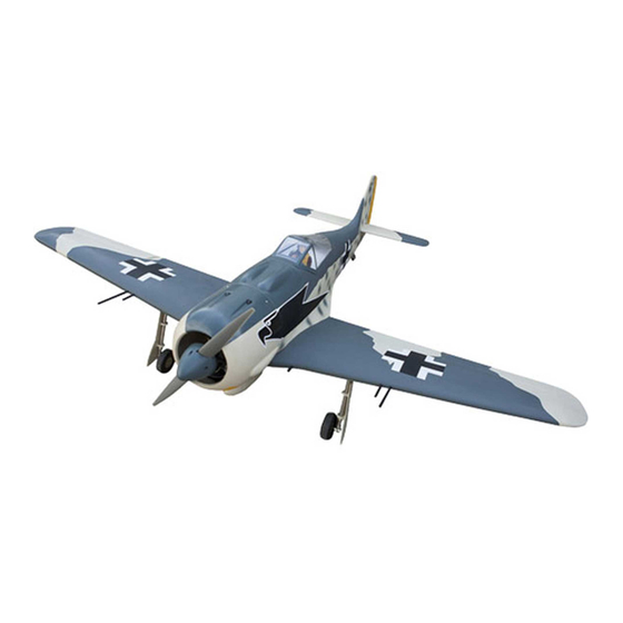
Speciications:
Wingspan---------------80 in (203.3 cm).
Wing area---------------1083.8 sq.in ( 69.9 sq.dm).
Weight-------------------19.8 lbs ( 9.0 kg).
Length-------------------62.9 in ( 159.7 cm).
Engine-------------------50cc
Motor size---------------Power 360
Radio--------------------8 channels with 10 servos.
Electric Power Conversion Optional.
1
Advertisement
Table of Contents

Related Manuals for SG Models FOCKE-WULF FW190


Summary of Contents for SG Models FOCKE-WULF FW190
- Page 1 A S S E M B L Y M A N U A L Code: SEA257 “ Graphics and speciications may change without notice ”. Speciications: Wingspan---------------80 in (203.3 cm). Wing area---------------1083.8 sq.in ( 69.9 sq.dm). Weight-------------------19.8 lbs ( 9.0 kg). Length-------------------62.9 in ( 159.7 cm).
-
Page 2: Kit Contents
Instruction Manual. INTRODUCTION. hank you for choosing the FOCKE-WULF FW190 ARF by SG MODELS . he FOCKE- WULF FW190 was designed with the intermediate/advanced sport lyer in mind. It is a semi scale airplane which is easy to ly and quick to assemble. he airframe is conventionally built using balsa, plywood to make it stronger than the average ARF, yet the design allows the aero- plane to be kept light. -
Page 3: Additional Items Required
KIT CONTENTS. HINGING THE FLAP. SEA25701 Fuselage SEA25702 Wing set SEA25703 Tail set SEA25704 Canopy SEA25705 Cowling SEA25706 Aluminium tube SEA25707 Pilot ADDITIONAL ITEMS REQUIRED. � 33cc-38cc gasoline engine. � Power 160 � Computer radio with 10 servos. � Glow plug to suit engine. �... -
Page 4: Wing Assembly
Focke- Wulf FW190 Instruction Manual. INSTALL FLAP CONTROL HORN. Install the lap control horn using the same method as same as the aileron con- trol horns. Fiberglass control horn INSTALL THE AILERONS CONTROL HORN. Fiberglass control horn Epoxy. Epoxy. WING ASSEMBLY. Please see below pictures. -
Page 5: Installing The Aileron Servos
INSTALLING THE AILERON SERVOS. Epoxy. Servos Small weight Thread Because the size of servos difer, you may need to adjust the size of the precut opening in the mount. he notch in the sides of the mount allow the servo lead to pass through. - Page 6 Focke- Wulf FW190 Instruction Manual. C/A glue 8) Remove the string from the wing at 4) Apply 2-3 drops of thin C/A to each the servo location and use the tape to at- of the mounting holes. Allow the C/A to tach it to the servo extension lead.
-
Page 7: Aileron Pushrod Installation
AILERON PUSHROD 9) Set the aileron hatch in place and use a INSTALLATION. Phillips screw driver to install it with four wood screws. Please see below pictures. 2x10mm 50mm M3 lock nut. M3 clevis. INSTALLING THE FLAP SERVO. Repeat the procedure for the lap servo. - Page 8 Focke- Wulf FW190 Instruction Manual. INSTALLING THE FLAP PUSHROD. Cut. Repeat the procedure for the aileron pushrod. M3 clevis. M3 lock nut. STANDARD RETRACTABLE LANDING GEAR. Please see below pictures.
- Page 9 Epoxy. Collar. 3x25mm Collar. Epoxy.
- Page 10 Focke- Wulf FW190 Instruction Manual. 3x10mm 50mm M3 clevis. M3 lock nut. Insert bomb onto the wing.
- Page 11 Epoxy. Insert the wing gun onto the wing. Epoxy.
- Page 12 Focke- Wulf FW190 Instruction Manual. Epoxy. OPTIONAL ELECTRIC RETRACT LANDING GEAR 33cc. Electric retract landing gear is not in- cluded in this kit, however it is a very popular add-on as optional. If you want to use retracts in your FW190, we recom- mend that you buy a good set of electric retracts as the Himark AM07 Main Gear shown as below.
- Page 13 3x25mm...
-
Page 14: Installing The Fuselage Servos
Focke- Wulf FW190 Instruction Manual. INSTALLING THE FUSELAGE SERVOS. Because the size of servos difer, you may need to adjust the size of the precut opening in the mount. he notch in the sides of the mount allow the servo lead to pass through. - Page 15 THROTTLE SERVO ARM 3/32” Hole. INSTALLATION. Install adjustable servo connector in the servo arm as same as picture below: Loctite secure. Adjustable servo connector. Servo arm. Trim and cut. hrottle servo arm. Switch. Elevator servo arm. Rudder servo arm. INSTALLING THE ENGINE SWITCH. Elevator servo arm.
-
Page 16: Installing The Stopper Assembly
Focke- Wulf FW190 Instruction Manual. Switch. Vent tube. Fuel pick up INSTALLING THE STOPPER Fuel fill tube. ASSEMBLY. 3) Carefully bend the second tube up at a 45º 1) Using a modeling knife, carefully cut angle. his tube is the vent tube. of the rear portion of one of the 3 nylon 4) Test it the stopper assembly into the tank. - Page 17 7) Slide the fuel tank into the fuselage. Guide the lines from the tank through the hole in the irewall. Balsa wood-front. Use a 1/4 bit to drill the engine mounting holes. Remove mounting template from ie- wall. Firewall shown with mounting holes Epoxy drilled ready for engine mounting.
-
Page 18: Mounting The Engine
Focke- Wulf FW190 Instruction Manual. 8) Drill a hole for the throttle pushrod. Vent tube. 170mm Fuel pick up tube. Fuel ill tube. 5x90mm 9) Connect the lines from the tank to the en- gine and muler. he vent line will connect to the muler and the line from the clunk to the carburetor. - Page 19 COWLING. Please see these below pictures. Reinstall the servo horn by sliding the connector over the pushrod wire. Center the throttle stick and trim and install the servo horn perpendicular to the servo center line. Move the throttle stick to the closed po- sition and move the carburetor to closed.
- Page 20 Focke- Wulf FW190 Instruction Manual. 4) Install the muler and muler extension onto the engine and make the cutout in the cowl for muler clearance. Connect the fuel and pressure lines to the carburetor, muler and fuel iller valve. Secure the cowl to fuse- lage using the M3x10mm socket head screws.
- Page 21 ELECTRIC POWER CONVERSION. 1) Locate the items neccessary to install the electric power conversion included with your model. 6.5mm Locate the laser cut engine mounting template. Align mounting template to front of irewall. 2) Recommend the items necessary to in- stall the electric power conversion parts included with your model.
- Page 22 Focke- Wulf FW190 Instruction Manual. Blind nut. M5x25mm and washers. 4) Attach the motor to the front of the electric motor box using four 4mm blind nut, four M4x20mm hex head bolts to se- M4x20mm cure the motor. Please see picture shown. Epoxy 170 mm hen, use 5.5mm drill bit to enlarge the...
-
Page 23: Installing The Spinner
5) Attach the speed control to the side of the motor box using two-sided tape Open the air exit hole. and tie wraps. Connect the appropriate leads from the speed control to the mo- tor. Make sure the leads will not interfere with the operation of the motor. -
Page 24: Hinging The Elevator
Focke- Wulf FW190 Instruction Manual. HINGING THE ELEVATOR. Fiberglass control horn hin CA. INSTALL RUDDER CONTROL HORN. Repeat steps to install the rudder control horn as same as steps done for ailerons. INSTALL ELEVATOR CONTROL HORN. Install the elevator control horn using the same method as same as the aileron Fiberglass control horn control horns. -
Page 25: Installing Horizontal Stabilizer
hin CA. Epoxy. INSTALLING RUDDER HINGE. Glue the rudder hinges in place using INSTALLING HORIZONTAL the same techniques used to hinge the el- STABILIZER. evator. Use Epoxy Glue to glue the Horizontal Stabilizer to the fuselage. -
Page 26: Elevator Pushrod Installation
Focke- Wulf FW190 Instruction Manual. Vertical ELEVATOR PUSHROD Stabilizer. Horizontal 90º INSTALLATION. Stabilizer. 1) Locate items necessary to install eleva- tor pushrod. Elevator control horn. 2) Elevator pushrods assembly as pic- tures below. 4x12mm 950mm... -
Page 27: Rudder Pushrod Installation
M3 Lock nut. M3 clevis. 995mm M3 clevis. M3 Lock nut. Elevator pushrod. RUDDER PUSHROD INSTALLATION. Rudder pushrod. 1) Locate items necessary to install rud- der pushrod. MOUNTING THE TAIL WHEEL. Rudder control horn. 2) Rudder pushrods assembly as pictures below. - Page 28 Focke- Wulf FW190 Instruction Manual. Steering arm. Tail gear. 820m m M3 lock nut M3 clevis...
- Page 29 2) A scale pilot is included with this ARF. he Pilot included itting well to the cockpit. (or you can order others scale pilot igures made by SG Models. hey are available at SG Models distributors.) If you are going to install a pilot igure, please use a sanding bar to sand the base of the igure so that it is lat.
-
Page 30: Apply The Decals
Focke- Wulf FW190 Instruction Manual. 4) Position the canopy onto the fuselage. Trace around the canopy and onto the fu- Battery. selage using a felt-tipped pen. Carefully cut and remove covering material from the fuselage where the canopy makes contact, exposing the bare wood. hen permanently glue the canopy in place with epoxy glue or special “canopy glue”. -
Page 31: Control Throws
Lit the model. If the tail drops when BALANCING. you lit, the model is “tail heavy” and you must add weight* to the nose. If the nose 1) It is critical that your airplane be drops, it is “nose heavy” and you must balanced correctly. - Page 32 Focke- Wulf FW190 Instruction Manual.
-
Page 33: Flight Preparation
A) Plug in your radio system per the 2) Check every bolt and every glue manufacturer’s instructions and turn joint in the FOCKE-WULF FW190 everything on. to ensure that everything is tight and well bonded. - Page 34 Focke- Wulf FW190 Instruction Manual. If you have any queries, or are interested in our products, please feel free to contact us Factory : 12/101A - Hamlet 4 - Le Van Khuong Street - Dong hanh Ward - Hoc Mon District - Ho Chi Minh City - Viet Nam. Oice : 62/8 Ngo Tat To Street - Ward 19 - Binh hanh District - Ho Chi Minh City - Viet Nam Phone : 848 - 86622289 or 848- 36018777...
Need help?
Do you have a question about the FOCKE-WULF FW190 and is the answer not in the manual?
Questions and answers