Table of Contents
Advertisement
Quick Links
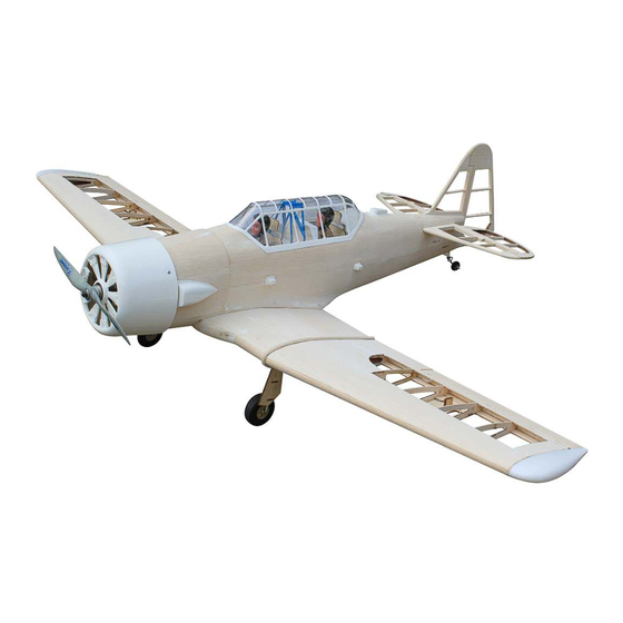
ASSEMBLY MANUAL
Speciications:
Wingspan-------------------- 62.9 in--------------------- 159 cm.
Length------------------------ 43.6 in--------------------- 110.8 cm.
Wing area-------------------- 620 sq.in------------------ 40.0 sq.dm.
Weight------------------------ 6.2 - 7.7 lbs--------------- 2.8 - 3.5 kg.
Recommended R/C -------- 10-15cc.
Radio System required 6 channels with 6 servos.
Code : MSK01.110
.40 - .52 cu.in / 2 stroke.
.72 - .82 cu.in / 4 stroke.
1
Advertisement
Table of Contents

Related Manuals for SG Models Master Scale kit Edition AT-6 Texan 63 10-15cc


Summary of Contents for SG Models Master Scale kit Edition AT-6 Texan 63 10-15cc
- Page 1 Code : MSK01.110 ASSEMBLY MANUAL Speciications: Wingspan-------------------- 62.9 in--------------------- 159 cm. Length------------------------ 43.6 in--------------------- 110.8 cm. Wing area-------------------- 620 sq.in------------------ 40.0 sq.dm. Weight------------------------ 6.2 - 7.7 lbs--------------- 2.8 - 3.5 kg. Recommended R/C -------- 10-15cc. .40 - .52 cu.in / 2 stroke. .72 - .82 cu.in / 4 stroke.
- Page 2 Instruction Manual. Master Scale kit Edition AT-6 Texan 63” 10-15cc INTRODUCTION - Congratulations and thank you for purchasing the Master Scale kit Edition AT-6 Texan 63” 10-15cc We are pleased to bring you this scale AT-6 Texan 63” 10-15cc. with this kit you can achieve whatever level of detail you like.
-
Page 3: Die-Cut Patterns
DIE-CUT PATTERNS 2.7mm balsa plywood 10 00 mmx250mm (1 per kit) 2.7mm balsa plywood 1000 mmx250mm (1 per kit) 2.7mm balsa plywood 1000 mmx250mm (1 per kit) 2.7mm balsa plywood 1000 mmx250mm (1 per kit) - Page 4 Instruction Manual. Master Scale kit Edition AT-6 Texan 63” 10-15cc DIE-CUT PATTERNS 3mm plywood 900 mmx250mm (1 per kit) 3mm plywood 900 mmx250mm (1 per kit) 2mm balsa plywood 10 00 mmx250mm (1 per kit) 2.5mm balsa sheet 500mx100mmm (1 per kit) 1mm plastic (1 per kit) 8mm balsa sheet 700mx100mmm (1 per kit)
- Page 5 DIE-CUT PATTERNS 2mm balsa sheet 100mm x100mmm (2 per kit) 2mm balsa sheet 100mm x100mmm (2 per kit) 2mm balsa sheet 1000mm x100mmm (2 per kit) 2mm balsa sheet 1000 mmx100mmm (1 per kit) 2mm balsa sheet 1000 mmx100mmm (1 per kit) 2mm balsa sheet 1000 mmx100mmm (1 per kit) 2mm balsa sheet 1000 mmx100mmm (1 per kit)
- Page 6 Instruction Manual. Master Scale kit Edition AT-6 Texan 63” 10-15cc DIE-CUT PATTERNS 2mm balsa sheet 1000 mm x100mmm (2 per kit) 2mm balsa sheet 1000mmx100mmm (2 per kit) 2mm balsa sheet 1000mmx100mmm (1 per kit) 2mm balsa sheet 1000mmx100mmm (1 per kit) PREPARE BEFORE BUILDING Please kindly see the plan drawing and compare to die-cut pattern to pick the parts of fuselage, the parts of wing, the parts of rudder and stabilizer.
-
Page 7: Build The Fuselage
Locate and assemble F1C, F1D, F1E, F1F to BUILD THE FUSELAGE irewall F1 by epoxy glue. (Photo 3,4). NOTE: he small point is regulations for the right side. As if you were sitting in the cockpit and distinguish let side and right side of model. NOTE: Regulations for the right side. - Page 8 Instruction Manual. Master Scale kit Edition AT-6 Texan 63” 10-15cc Locate and assemble wing mount F35A to F35B by epoxy glue. (Photo 7,8). Locate and assemble F3B behind F3A by epoxy glue. (Photo 11,12). Locate and assemble F7B behind F7 by epoxy glue.
- Page 9 Locate and assemble tab F34A to F34B (include Locate and assemble Pronged T-Nuts M4 to 4 sets) by epoxy glue. hen assemble them to F1C engine holes of F1 (irewall) ; as photo shown (Photo 13,14). (photo 16). Pronged T-Nuts M3 to holes of F37 as photo shown (photo 16).
- Page 10 Instruction Manual. Master Scale kit Edition AT-6 Texan 63” 10-15cc Locate and assemble MO1, MO2, MO3, MO4 by epoxy glue to become a mount box. hen, reinforce by two triangle balsa bars. (Photo 19,20). * Build the fuselage. As shown (photo 23). All parts are available for fuselage assembly.
- Page 11 Locate and assemble F2 to S2 as (Photo 25,26). Locate and assemble F4, F5 to S2 (the right fuselage side) as (Photo 28). NOTE: he small point is regulations for the right side. Locate and assemble F2, F3, F4, F5 to S1 (the let fuselage side) as (Photo 29).
- Page 12 Instruction Manual. Master Scale kit Edition AT-6 Texan 63” 10-15cc Locate and assemble F7 to S1, S2 as (photo 31, 32). Locate and assemble F1 to S1, S2 as (photo 36, 37). NOTE: he small point is regulations for the Locate and assemble F1, F27, F28, F29 to S1, S2 right side.
- Page 13 Locate and assemble wing mount F35 (include F35A, F35B) to fuselage by epoxy as (photo 41,42). Reinforce the triangle balsa bar at out side where the perpendicular angle of F1 and S1; the perpen- dicular angle of F1 and S2 so that ensure strong for F1 as (photo 38).
- Page 14 Instruction Manual. Master Scale kit Edition AT-6 Texan 63” 10-15cc Locate and assemble F31 (let and right) to fuselage by epoxy as (photo 43). Locate and assemble F4A, F5A to fuselage as (photo 47). Weld two half of sheet F32 to become a sheet by CA glue.
- Page 15 F10 F11 F12 F11A Locate and assemble the former, one ater an- Locate and assemble F14A as (photo 53). other in order F7- F12, they are gone through the aluminum square strip as (Photo 50). NOTE: he small point is regulations for the right side. F14A Locate and assemble F25 as (photo 54).
- Page 16 Instruction Manual. Master Scale kit Edition AT-6 Texan 63” 10-15cc Locate and assemble F26 as (photo 56). Locate and assemble F37 as (photo 60). Locate and assemble F15, F16 as (photo 57). Locate and assemble FS5 (servo mount) as (photo 61). Locate and assemble F11A as (photo 58,59).
- Page 17 Attach the plastic pushrod tube to the push- * Sheeting of the fuselage (cover to the ribs of rod hole at each former fuselage as photo shown fuselage). (photo 62). Weld together three diference pieces SH1 become a sheet (let and right) by CA glue as pho- to shown.
- Page 18 Instruction Manual. Master Scale kit Edition AT-6 Texan 63” 10-15cc Bend the balsa sheet go to the curve of top area. hen, add CA glue and use the inger at this place until the glue dries as photo shown . Do the same for the other half of the top area, so that the balsa sheet keep ixed fuselage.
- Page 19 Put the sheet SH6 at area of fuselage as photo shown (photo 75). Bend the balsa sheet SH6 go to the curve toward area. hen, add CA glue and use the inger at this place until the glue dries as photo shown. Do the same for the other half of toward area, so that the balsa sheet keep ixed fuselage.
- Page 20 Instruction Manual. Master Scale kit Edition AT-6 Texan 63” 10-15cc THE WING * Landing gear mount. Locate and apply CW19A (2pcs) to CW19 by CA as photo shown (photo 1,2). CW19A CW19A CW19 Finish as (photo 5). Pick some parts as shown (photo 6) (CW1- CW22) so that prepare for assemble the center wing.
- Page 21 Locate and assemble CW8 (leading edge) as (photo 11). Locate and assemble CW14 (trailing edge) as (photo 9). Locate and assemble CW10 (reinforce leading edge) as (photo 12). Locate and assemble CW9 (leading edge) as (photo 10). Locate and assemble CW13 (cap strips) at top wing and bottom wing as (photo 13).
- Page 22 Instruction Manual. Master Scale kit Edition AT-6 Texan 63” 10-15cc Locate and assemble CW19 (gear mount) by Locate and apply CW11 (reinforce for servo epoxy glue as (photo 14,15). mount) by epoxy glue as (photo 17,18). Locate and apply CW4A (reinforce for gear Locate and apply CW20 (reinforce for gear area) by epoxy glue as (photo 16).
- Page 23 CW20 CW20 CW20 Locate and apply the square stock (reinforce for Locate and apply CW8A 8mm balsa (reinforce gear mount) at inside angle of CW19 and CW20 by for leading edge) by epoxy glue as (photo 24). epoxy glue. hen, add a little epoxy glue as (photo 21,22,23).
- Page 24 Instruction Manual. Master Scale kit Edition AT-6 Texan 63” 10-15cc Locate and assemble CW23 balsa (4pcs) (let Locate and assemble wing tube. Light sanding and right) by epoxy glue as (photo 26). the wing tube to it can through to holes easily as photo shown (photo 29).
- Page 25 Weld 4 parts of CW16, together to become a sheet . Do like this for 4 parts of CW17 (Photo 31,32). CW16 (1) CW16 (2) CW16 (3) CW16 (4) Locate and assemble CW15 as (photo 35,36). CW17 CW16 Cover sheet CW16 to wing at bottom side. hen, CW17 to wing at top side as photo 33,34).
- Page 26 Instruction Manual. Master Scale kit Edition AT-6 Texan 63” 10-15cc Locate and assemble the rib, one ater another in Prepare leading edge W17 and trailing edge order W2-W9 (two side wing) to W18. as (photo W20, W21 and cap strip W19 as (photo 41). 38,39,40).
- Page 27 Locate and assemble trailing edge W20, W21. Locate and assemble the lock of wing tube W29 (Photo 45). . (Photo 48). Locate and assemble cap strip W19 (top and Locate and assemble W30 (the ring washer of bottom). (Photo 46,47). wing tube) to ix the tube.
- Page 28 Instruction Manual. Master Scale kit Edition AT-6 Texan 63” 10-15cc Light sanding until the balsa strip look like seamless W17. (Photo 53). Locate and assemble W12, W13 (servo mount) as (photo 51). Try to test center wing and side wing it together by use wing tube to join the two panels rib’s frame.
- Page 29 * Finishing he Outer Wing Panels. Weld two parts of sheet W25 together to be- come one. hen, cover to bottom side at servo hatch’s place as (photo 59,60). Locate and cover sheet W27 at top side wing as (photo 56). Weld two parts of sheet W22 together to be- come one.
- Page 30 Instruction Manual. Master Scale kit Edition AT-6 Texan 63” 10-15cc W24 (1) W24 (2) Sanding at the root for lat and remove the excess part of sheet. (Photo 65). Weld two parts of sheet W26 together to be- come one. hen, cover to top and bottom side as Locate and apply W1 at the root and W10 at the (photo 63,64).
- Page 31 Sanding a round the wing for smooth and Locate and assemble W11 (tip) to the plastic tip rounded leading edge. (Photo 68). cover by CA glue as (photo 71,72). Attach the aileron ( balsa stock) to wing by CA hinge. (Photo 69). Cut down the excess plastic parts and sanding for lat the tip as (photo 73).
- Page 32 Instruction Manual. Master Scale kit Edition AT-6 Texan 63” 10-15cc Cut down the excess plastic parts and sanding Remove the vertical wood excess by blade as for lat the tip as (photo 74). (photo 77,78). Locate and apply three ribs together, one ater another one W1B-W1A-W1B as (photo 75,76).
- Page 33 Locate and assemble the rib between the wing center and wing side (let and right) as (photo 80). Assemble the servo mount hatch. (Photo 81,82, 83,84).
- Page 34 Instruction Manual. Master Scale kit Edition AT-6 Texan 63” 10-15cc THE STABILIZER AND ELEVATOR Prepare for assemble the Stabilizer and Elevator. Balsa 8mmx10mm x50mm spars. Balsa 8mmx10mm x230mm spars. Balsa 8mmx10mm x230mm spars. he laser cut special parts are available from code ST4 –...
- Page 35 Locate position of paper hinge for Stabilizer and Elevator as plan. hen, sawn the slot (for 6 hinges) by the blade tool (Photo 10,11). Locate and assemble the Elevator as the plan. Step by step do it one ater another in order 1-3. Use the nail to plug in keep the rib on the paper plan and add CA glue.
-
Page 36: Fin And Rudder
Instruction Manual. Master Scale kit Edition AT-6 Texan 63” 10-15cc Finish set of horizon stab. (Photo 13). Locate and assemble the Rudder as the plan. Step by step do it one ater another in order 1-6. Use the nail to plug in keep the rib on the paper plan and add CA glue. - Page 37 Locate and assemble T1 as the (photo 4). SET UP Cut of the excess balsa wood part, rounded the edge around of Fin and Rudder by sanding tool. Sanding to smooth (not rough) at interface on (Photo 5). fuselage (the edges of fuselage where the wing panel intersect to the fuselage) as photo shown (Photo 1).
- Page 38 Instruction Manual. Master Scale kit Edition AT-6 Texan 63” 10-15cc Locate and assemble the 8mm dowel at wing Use the sharp screw to take point of mark so root of center wing for two sides (let and right) as that locating of hole. hen, put the wing on fuse- (photo 3).
- Page 39 Apply F17 at rear of fuselage. hen, sanding rounded as (photo 9). Apply F14B at fuselage as (photo 13). Assemble F14A at rear of fuselage at intersect to stabilizer as (photo 10). F14B Install the Stabilizer to fuselage. hen apply F40 at rear so that the gap (between stabilizer and F40) is 5mm.
- Page 40 Instruction Manual. Master Scale kit Edition AT-6 Texan 63” 10-15cc Locate and assemble as (photo 16). Install the box of in to fuselage.hen, install the in to slot of box. Push the in toward rear to end of fuselage. Insert T3 to slot of box, front the in. (Photo 19,20).
- Page 41 Locate and attach two plastic gear ix pieces to Locate and assemble the part 1mm plastic (the the plywood gear door as (photo 22). cockpit simulation detail) to become the plastic frame. (Photo 25,26,27,28). Locate and assemble F38 (simulation control panel at cockpit area) to the plastic frame.
-
Page 42: Final Assembly
Instruction Manual. Master Scale kit Edition AT-6 Texan 63” 10-15cc FINAL ASSEMBLY. NOTE: To avoid scratching your new aero plane we suggest that you cover your work- bench with an old towel. Keep a couple of jars or bowls handy to hold the small parts af- ter you open the bags. -
Page 43: Hinging The Ailerons
NOTE: To avoid scratching your new aero- plane we suggest that you cover your workbench with an old towel. Keep a couple of jars or bowls handy to hold the small parts after you open the bags. T-pin. Please trial fit all parts. Make sure you have the correct parts and that they fit and are aligned properly before gluing! This will ensure proper assembly as... -
Page 44: Hinging The Rudder
Instruction Manual. Master Scale kit Edition AT-6 Texan 63” 10-15cc Apply epoxy glue. C/A glue. 5) Turn the wing panel over and deflect the aileron in the opposite direction from the opposite side. Apply thin C/A glue to each hinge, making sure that the C/A penetrates into both the aileron and wing panel. - Page 45 Install the wing edge to the wing. AILERON CONTROL HORN Masking tape. Aileron control horn: See pictures below 2 sets. 3x35mm. CONTROL HORN M3 SCREW. Epoxy Epoxy ALUMINUM WASHER 18mm M3 LOCK NUT ALUMINUM WASHER...
-
Page 46: Rudder Control Horn
Instruction Manual. Master Scale kit Edition AT-6 Texan 63” 10-15cc Elevator control horn. RUDDER CONTROL HORN. Rudder control horn: ELEVATOR CONTROL HORN. Using the same techniques used aileron control horn. See picture below. Install the elevator control horn using the same method as with the aileron control horns. -
Page 47: Pushrod Installation
Remove covering. Rudder control horn. SERVO GEAR INSTALLATION. Metal connector. Electric wire. 25mm. Servo arm. Servo for retractable only. Wing bottom. PUSHROD INSTALLATION. Adjustable servo connector. Servo arm. loctile M3x25mm. secure. 3mm. 25mm. Remove covering. - Page 48 Instruction Manual. Master Scale kit Edition AT-6 Texan 63” 10-15cc Metal clevis. Pushrod. M3 lock. 2 x 6 mm. 3 x 25 mm. Open Position Servo arm.
-
Page 49: Wing Assembly
Close Position 12 mm. Servo arm. Repeat procedure for other landing gear. Epoxy. WING ASSEMBLY. epoxy. -
Page 50: Engine Mount Installation
Instruction Manual. Master Scale kit Edition AT-6 Texan 63” 10-15cc epoxy. Mark and drill 4 holes for engine mount. Insert 4 blind nuts to firewall. M4x30mm. ENGINE MOUNT INSTALLATION. See pictures below.Make yourself the template of your engine on paper. INSTALLING THE STOPPER ASSEMBLY. - Page 51 4) Carefully heat the vent tube using a heat gun or lighter to permanently set the angle of the tube. Vent tube. Fuel Pick up Tube. Fuel Fill Tube. 2) Using a modeling knife, cut one length of When the stopper assembly is in- silicon fuel line.
-
Page 52: Installing The Battery
Instruction Manual. Master Scale kit Edition AT-6 Texan 63” 10-15cc INSTALLING THE BATTERY. Battery. You should mark which tube is the vent and which is the fuel pickup when you attach fuel tubing to the tubes in the stopper. Once the tank is installed inside the fuselage, it may be difficult to determine which is which. - Page 53 M3 x 25 mm. Engine 2 stroke : Trim and cut. M3 x 25 mm. Pushrod wire. M3 x 25 mm.
- Page 54 Instruction Manual. Master Scale kit Edition AT-6 Texan 63” 10-15cc COWLING. M3 x 10 mm. Dummy Engine 1.5mm wire (needle valve). Trim and cut. Electric Conversion (Ep Power) (OPTION). Diametrer = 4 mm. Trim and cut. M3 x10 mm.
- Page 55 M3 x 15 mm. Epoxy. Epoxy. Epoxy. 115mm. Electric motor.
-
Page 56: Installing The Aileron Servos
Instruction Manual. Master Scale kit Edition AT-6 Texan 63” 10-15cc Balsa block. Balsa block. Electric motor. INSTALLING THE AILERON SERVOS. Speed control. M3 x 15mm. Small weight. Servos. Thread. Battery. Small weight. SPINNER INSTALLATION. String. - Page 57 Small weight. Aileron Servo. String. Attach the string to the servo lead and carefully thread it through the wing. M2 x 12 mm. M3 x15mm. INSTALLING THE FUSELAGE SERVOS- THROTTLE SERVO ARM INSTALLATION. SWITCH. ) Install adjustable servo connector in Switch.
-
Page 58: Installing The Horizontal Stabilizer
Instruction Manual. Master Scale kit Edition AT-6 Texan 63” 10-15cc Elevator servo . Throttle servo arm. Pen. Rudder servo. INSTALLING THE HORIZONTAL STABILIZER. Trim and cut. Epoxy. Draw center line. When cutting through the covering to re- move it, cut with only enough pressure Epoxy. -
Page 59: Installing The Vertical Stabilizer
Pen. INSTALLING THE VERTICAL STABILIZER. Remove covering. Epoxy. When cutting through the covering to re- move it, cut with only enough pressure to only cut through the covering itself. Cutting into the balsa structure may weaken it. Put the vertical stabilizer into the in the top of the horizontal fin. - Page 60 Instruction Manual. Master Scale kit Edition AT-6 Texan 63” 10-15cc Epoxy. INSTALLATION THE PUSHROD. 90mm. 8mm. Trim and cut. 8mm. 80mm. 80mm. M2 Lock nut. M2 clevis. Wire keeper. Attach to servo arm in fuselage. snap keeper. M2 lock nut. Repeat the procedure for the other wing half.
- Page 61 Rudder pushrod. M2 lock nut. Elevator and rudder pushrods assembly follow pictures below. M2 clevis. M2 Lock nut. 80mm. Wire keeper. Attach to servo arm in fuselage. Throttle. Elevator. Rudder.
- Page 62 Instruction Manual. Master Scale kit Edition AT-6 Texan 63” 10-15cc Fuel tank. 6mm. 2mm. 110mm. C/A glue. MOUNTING THE TAIL WHEEL. See picture below. C/A glue. 6mm. 6mm. M2 x 20 mm. M3 x 12 mm. INSTALLATION PILOT. 2pcs. Epoxy. Epoxy.
- Page 63 C/A glue. 55mm. 210mm. M2 x 6mm. 45mm. C/A glue. C/A glue.
-
Page 64: Installing The Receiver
Instruction Manual. Master Scale kit Edition AT-6 Texan 63” 10-15cc 90mm. C/A glue. ATTACHMENT WING-FUSELAGE. Bolt the to fuselage.See pictures below. Wing bolt. INSTALLING THE RECEIVER. 1) Plug the six servo leads and the switch lead into the receiver. Plug the battery pack lead into the switch also. -
Page 65: Control Throws
CONTROL THROWS Rudder: Ailerons: High Rate : High Rate : Right : 20mm Up : 12mm Let : 20mm Down : 12mm Low Rate : Low Rate : Right : 15mm Up : 10mm Let : 15mm Down : 10mm Elevator: High Rate : Up : 12mm... -
Page 66: Flight Preparation
Instruction Manual. Master Scale kit Edition AT-6 Texan 63” 10-15cc FLIGHT PREPARATION PREFLIGHT CHECK 1) Completely charge your transmitter and Check the operation and direction of the eleva- receiver batteries before your irst day of lying. tor, rudder, ailerons and throttle. 2) Check every bolt and every glue joint in A) Plug in your radio system per the manu- Master Scale kit Edition AT-6 Texan... - Page 67 If you have any queries, or are interested in our products, please feel free to contact us Factory : 12/101A - Hamlet 4 - Le Van Khuong Street - Dong hanh Ward - Hoc Mon District - Ho Chi Minh City - Viet Nam. Oice : 62/8 Ngo Tat To Street - Ward 19 - Binh hanh District - Ho Chi Minh City - Viet Nam Phone : 848 - 86622289 or 848- 36018777...
Need help?
Do you have a question about the Master Scale kit Edition AT-6 Texan 63 10-15cc and is the answer not in the manual?
Questions and answers