Table of Contents
Advertisement
Quick Links
Code : SEA 330
ASSEMBLY MANUAL
Specifications:
Wingspan--------------- 95.0 in (241.2 cm).
Wing area--------------- 1191.0 sq.ins (76.8 sq.dm).
Weight------------------- 24.2 lbs (11.0 kg).
Length------------------- 75.7 in (192.3 cm).
Engine/Motor size----- 20cc gasoline engine.
Radio--------------------- 11 channels with 14 servos.
1
Advertisement
Table of Contents

Subscribe to Our Youtube Channel
Related Manuals for SG Models Mitchell B-25 for 20cc engines-95


Summary of Contents for SG Models Mitchell B-25 for 20cc engines-95
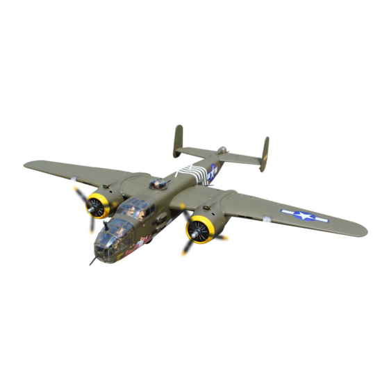
- Page 1 Code : SEA 330 ASSEMBLY MANUAL Specifications: Wingspan--------------- 95.0 in (241.2 cm). Wing area--------------- 1191.0 sq.ins (76.8 sq.dm). Weight------------------- 24.2 lbs (11.0 kg). Length------------------- 75.7 in (192.3 cm). Engine/Motor size----- 20cc gasoline engine. Radio--------------------- 11 channels with 14 servos.
-
Page 2: Kit Contents
Mitchell B-25 -for 20cc engines-95” Instruction Manual INTRODUCTION ARTF by SG MOD- Thank you for choosing the Mitchell B-25 -for 20cc engines-95” ELS .The was designed with the intermediate/advanced Mitchell B-25 -for 20cc engines-95” sport flyer in mind. It is a semi scale airplane which is easy to fly and quick to assem- ble. -
Page 3: Hinging The Aileron
KIT CONTENTS HINGING THE AILERON SEA330 Mitchell B-25 -for 20cc engines-95” Note : The control surfaces, including the ai- lerons, elevators, and rudder, are prehinged 1. Fuselage with hinges installed, but the hinges are not 2. Wing set (2) glued in place. It is imperative that you prop- 3. - Page 4 Mitchell B-25 -for 20cc engines-95” Instruction Manual Deflect the aileron and completely saturate each hinge with thin C/A glue. The ailerons front surface should lightly contact the wing during this procedure. Ideally, when the hinges are glued in place, a 1/64” gap or less will be maintained throughout the lengh of the aileron to the wing panel hinge line.
- Page 5 WING TIP BULBS Please see below pictures. CA glue They are designed to operate on volt- ages 12 volts. CA glue...
- Page 6 Mitchell B-25 -for 20cc engines-95” Instruction Manual Epoxy Fiberglass control horn INSTALL THE AILERONS INSTALL FLAP CONTROL HORN CONTROL HORN Install the flap control horn using the same method as same as the aileron con- trol horns. Fiberglass control horn Epoxy Epoxy...
- Page 7 Use drill bit in a pin vise to drill the INSTALLING THE ALLERON SERVOS mouting holes in the blocks. Apply 2-3 drops of thin C/A to each of the mounting holes. Allow the C/A to cure without using accelerator. C/A glue Minimum servo spec.
- Page 8 Mitchell B-25 -for 20cc engines-95” Instruction Manual Apply 1-2 drops of thin C/A to each of the mounting tabs. Allow the C/A to cure without using accelerator. C/A glue Remove the string from the wing at the servo location and use the tape to attach it to the servo extension lead.
-
Page 9: Aileron Pushrod Installation
80mm AILERON PUSHROD INSTALLATION Please see below pictures. 80mm INSTALLING THE FLAP PUSHROD Repeat the procedure for the aileron pushrod. INSTALLING THE FLAP SERVO Repeat the procedure for the flap servo. - Page 10 Mitchell B-25 -for 20cc engines-95” Instruction Manual SET UP BOTTOM HATCH SYSTEM Please see below pictures.
-
Page 11: Engine Mount Installation
ENGINE MOUNT INSTALLATION Locate the items necessary to install the engine mount included with your model. Epoxy... - Page 12 Mitchell B-25 -for 20cc engines-95” Instruction Manual 3x10mm Thread locker glue 4x30mm Use four 4x30mm head bolts and four 4mm washers to attach the engine mount rails to the firewall. Tighten the screws . Make sure to use threadlock on the screws to help prevent them from vibrat- ing loose.
- Page 13 4x30mm Use a drill to drill the four holes in the engine mount rails. Position the engine with the drive washe (140mm) forward of the firewall as shown. 140mm...
-
Page 14: Installing The Stopper Assembly
Mitchell B-25 -for 20cc engines-95” Instruction Manual Reinstall the servo horn by sliding the Using a modeling knife, cut one length connector over the pushrod wire. Cent- of silicon fuel line. Connect one end of er the throttle stick and trim and install the line to the weighted fuel pick up and the servo horn perpendiular to the servo the other end to the nylon pick up tube. -
Page 15: Fuel Tank Installation
Test fit the stopper assembly into the tank. It may be necessary to remove some of the flashing around the tank opening using a modeling knife. If flashing is present, make sure none falls into the tank. With the stopper assembly in place, the weighted pick-up should rest away from the rear of the tank and move freely inside the tank. -
Page 16: Optional Retractable Landing Gear
Mitchell B-25 -for 20cc engines-95” Instruction Manual Set up sevor to pull the cover of the box. OPTIONAL RETRACTABLE LANDING GEAR If you want to use retracts in your Michell B-25-for 20cc engines 95”, it is a very popular add-on as optional, we rec- ommend that you buy a good set of elec- tric retracts as the Himark AM07 Main Gear and Himark AM08 Nose Gear... - Page 17 ELECTRIC RETRACTABLE LANDING GEAR Electric retractable landing gear is in- cluded in this kit shown as below. Main Gear. If you use the Himark Mair gear, please cut off so that length is 170mm shown as below. Epoxy 170mm...
- Page 18 Mitchell B-25 -for 20cc engines-95” Instruction Manual 3x15mm...
- Page 19 6x25mm Thread locker glue...
- Page 20 Mitchell B-25 -for 20cc engines-95” Instruction Manual 80mm...
- Page 21 1.5mm...
- Page 22 Mitchell B-25 -for 20cc engines-95” Instruction Manual 2x8mm 1.5mm 2x8mm...
- Page 23 3x10mm 3x10mm...
- Page 24 Mitchell B-25 -for 20cc engines-95” Instruction Manual 60mm...
- Page 25 COWLING Please see below pictures. 3x15mm...
- Page 26 Mitchell B-25 -for 20cc engines-95” Instruction Manual...
- Page 27 3x10mm...
- Page 28 Mitchell B-25 -for 20cc engines-95” Instruction Manual...
- Page 29 ELECTRIC POWER CONVERSION Locate the items neccessary to install the electric power conversion included with your model. Recommend the items necessary to in- M4x25mm and washers stall the electric power conversion parts included with your model. - Motor: 110 - 2000 Watts - Propeller: 17x8 ~ 19x10 Attach the motor to the front of the - ESC: 85A...
- Page 30 Mitchell B-25 -for 20cc engines-95” Instruction Manual Blind nut Then, use 5.5mm drill bit to enlarge the M4x20mm holes on the electric motor box. 5.5mm 140mm...
- Page 31 Balsa stick Epoxy 3x10mm...
- Page 32 Mitchell B-25 -for 20cc engines-95” Instruction Manual 6x25mm Thread locker glue...
- Page 33 STABILIZER SET INSTALLTION Please see below pictures. Minimum servo spec. Torque : 194 oz-in (14 kg-cm) @ 6.0V; 236 oz-in ( 17kg-cm) @ 7.4V ELEVATOR INSTALLTION SERVO...
- Page 34 Mitchell B-25 -for 20cc engines-95” Instruction Manual 2. 7. 1.5mm C/A glue 13 .
- Page 35 ELEVATOR PUSHROD HORN RUDDER SET INSTALLTION INSTALLATION Please see below pictures. 80mm...
- Page 36 Mitchell B-25 -for 20cc engines-95” Instruction Manual Minimum servo spec. Torque : 61.10 oz-in (4.4 kg-cm) @ 4.8V; 76.37 oz-in (5.5 kg-cm) @ 6.0V RUDDER PUSHROD HORN INSTALLATION Epoxy 50mm...
- Page 37 4x15mm...
- Page 38 Mitchell B-25 -for 20cc engines-95” Instruction Manual Epoxy PILOT INSTALLTION ON STABILIZER Please see below pictures. C/A glue...
- Page 39 INSTALLING THE ENGINE SWITCH Trim and cut INSTALLING THE RECEIVER SWITCH Install the switch into the precut hole in the side, in the fuselage. Switch 3/32” Hole. ELECTRIC GEAR NOSE INSTALLTION Trim and cut Please see below pictures. Switch...
- Page 40 Mitchell B-25 -for 20cc engines-95” Instruction Manual Minimum servo spec. Torque : 61.10 oz-in (4.4 kg-cm) @ 4.8V; 76.37 oz-in (5.5 kg-cm) @ 6.0V...
- Page 41 3x12mm NOSE GEAR INSTALLTION...
- Page 42 Mitchell B-25 -for 20cc engines-95” Instruction Manual 3x3mm 3x3mm...
- Page 43 Epoxy...
- Page 44 Mitchell B-25 -for 20cc engines-95” Instruction Manual C/A glue 2x8mm...
- Page 45 BOMB BAY DOOR SYSTEM INSTALLATION SERVO GEAR INSTALLATION Minimum servo spec. Torque : 91.65 oz-in (6.6 kg-cm) @ 4.8V; 113.87 oz-in (8.2 kg-cm) @ 6.0V...
- Page 46 Mitchell B-25 -for 20cc engines-95” Instruction Manual...
- Page 47 80mm...
- Page 48 Mitchell B-25 -for 20cc engines-95” Instruction Manual INSTALLATION COCKPIT, PILOT AND CANOPY Locate items necessary to install.
- Page 49 Epoxy...
- Page 50 Mitchell B-25 -for 20cc engines-95” Instruction Manual Epoxy Epoxy...
- Page 51 Epoxy Epoxy...
- Page 52 Mitchell B-25 -for 20cc engines-95” Instruction Manual...
- Page 53 Epoxy Epoxy...
- Page 54 Mitchell B-25 -for 20cc engines-95” Instruction Manual Epoxy Epoxy...
- Page 56 Mitchell B-25 -for 20cc engines-95” Instruction Manual Epoxy...
- Page 57 Epoxy...
- Page 58 Mitchell B-25 -for 20cc engines-95” Instruction Manual C/A glue COKPIT INSTALLATION ON TOP HATCH Locate items necessary to install.
- Page 59 Epoxy...
- Page 60 Mitchell B-25 -for 20cc engines-95” Instruction Manual Epoxy C/A glue...
-
Page 61: Install The Plastic Parts
INSTALL THE PLASTIC PARTS. Locate the items neccessary to install the plastic parts included with your models: Position the plastic parts onto the can- opy and fuselage and apply C/A glue and Epoxy hold the plastic parts secure until the glue fully cures. - Page 62 Mitchell B-25 -for 20cc engines-95” Instruction Manual GUN INSTALLATION TWO SIDE OF FUSLAGE Please see pictures below. Epoxy...
- Page 63 Epoxy Epoxy...
- Page 64 Mitchell B-25 -for 20cc engines-95” Instruction Manual...
- Page 65 Epoxy STABILIZER INSTALLATION INTO FUSELAGE Please see below pictures.
- Page 66 Mitchell B-25 -for 20cc engines-95” Instruction Manual 4x20mm Thread locker glue...
-
Page 67: Apply The Decals
ATTACHMENT WING-FUSELAGE Attach the aluminium tube into fuselage. APPLY THE DECALS 1) If all the decals are precut and ready to stick. Please be certain the model is clean and free from oily fingerprints and dust. Position decal on the model where desired, using the photos on the box and aid in their location. -
Page 68: Control Throws
Mitchell B-25 -for 20cc engines-95” Instruction Manual 3) With the model inverted, place your CONTROL THROWS fingers on the masking tape and carefully lift the plane. This is the point at which Ailerons: Rudder: your model should balance for your first High Rate : High Rate : flights. - Page 69 30-40mm 30-40mm 25-30mm Fuselage 25-30mm 20-25mm Wing 20-25mm 30mm 60mm...
-
Page 70: Flight Preparation
Mitchell B-25 -for 20cc engines-95” Instruction Manual FLIGHT PREPARATION PREFLIGHT CHECK 1) Completely charge your transmit- Check the operation and direction ter and receiver batteries before your of the elevator, rudder, ailerons and first day of flying. throttle. 2) Check every bolt and every glue A) Plug in your radio system per the joint in the Mitchell B-25 -for 20cc en-... - Page 71 If you have any queries, or are interested in our products, please feel free to contact us Factory : 12/101A - Hamlet 4 - Le Van Khuong Street - Dong Thanh Ward - Hoc Mon District - Ho Chi Minh City - Viet Nam. Office : 62/8 Ngo Tat To Street - Ward 19 - Binh Thanh District - Ho Chi Minh City - Viet Nam Phone : 848 - 86622289 or 848- 36018777...
Need help?
Do you have a question about the Mitchell B-25 for 20cc engines-95 and is the answer not in the manual?
Questions and answers