Table of Contents
Advertisement
Quick Links
Instruction Manual.
A S S E M B L Y M A N U A L
Code: SEA212
" Graphics and specifications may change without notice " .
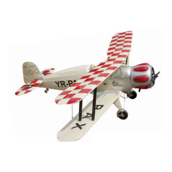
Specifications:
Wingspan---------------65.0 in (165 cm).
Wing area----------------1240.0 sq.in (80.0 sq.dm).
Weight--------------------11.0 lbs (5.0 kg).
Fuselage Length--------57.8 in (146.80cm).
Engine-------------------0.9cu.in - 2 stroke.
----------------------------1.2cu.in - 4 stroke.
----------------------------20-22cc gasoline engine
A
R
F
LMOST
EADY TO
LY
Radio--------------------4 channel with 6 servos.
1
Advertisement
Table of Contents

Subscribe to Our Youtube Channel
Related Manuals for SG Models Bucker Jungmeister SEA212


Summary of Contents for SG Models Bucker Jungmeister SEA212
- Page 1 Instruction Manual. A S S E M B L Y M A N U A L Code: SEA212 “ Graphics and specifications may change without notice ” . Specifications: Wingspan---------------65.0 in (165 cm). Wing area----------------1240.0 sq.in (80.0 sq.dm). Weight--------------------11.0 lbs (5.0 kg). Fuselage Length--------57.8 in (146.80cm).
-
Page 2: Kit Contents
Bunker Bu 133 INTRODUCTION. Thank you for choosing the BUNKER BU 133 ARF by SG MODELS . The BUNKER BU 133 was designed with the intermediate/advanced sport flyer in mind. It is a semi scale airplane which is easy to fly and quick to assemble. The airframe is conventionally built using balsa, plywood to make it stronger than the average ARF, yet the design allows the aeroplane to be kept light. -
Page 3: Hinging The Elevators
Instruction Manual. KIT CONTENTS. HINGING THE ELEVATORS. SEA21201 Fuselage 1) Locate the item for this sectiom of the SEA21202 Wing set manual. SEA21203 Tail set SEA21204 Canopy Hatch SEA21205 Cowling SEA21206 Wing tube SEA21207 Pilot 2) Carefully remove the elevator from one of the horizontal stabilizer panels. -
Page 4: Hinging The Rudder
Bunker Bu 133 Glue the hinge hinges in place using the same techniques used to hing the ailerons. Epoxy. HINGING THE RUDDER. INSTALL ELEVATOR CONTROL HORN. Glue the rudder hinges in place using Install the elevator control horn using the same techniques used to hinge the ai- the same method as same as the aileron lerons. -
Page 5: Installing The Fuselage Servos
Instruction Manual. INSTALL RUDDER CONTROL HORN. Repeat steps to install the rudder control horn as same as steps done for ailerons. Elevator. Rudder control horn. Throttle. Rudder. Elevator. THROTTLE SERVO ARM INSTALLATION. Install adjustable servo connector in the Epoxy. servo arm as same as picture below: Loctite secure. -
Page 6: Installing The Stopper Assembly
Bunker Bu 133 INSTALLING THE SWITCH RECEIVER. Install the switch into the precut hole in the side, in the fuselage. 3/32” Hole. Switch. INSTALLING THE STOPPER ASSEMBLY. 1) Using a modeling knife, carefully cut off the rear portion of one of the 3 nylon tubes leaving 1/2”... -
Page 7: Fuel Tank Installation
Instruction Manual. 7) Slide the fuel tank into the fuselage. Guide the lines from the tank through the hole in the firewall. 8) Use plywood template to hold in place the fuel tank with C/A glue to secure the fuel tank inside the fuselage. -
Page 8: Engine Mount Installation
Bunker Bu 133 MOUNTING THE ENGINE - 2 stroke. 1) Position the engine with the drive washer (145mm) forward of the firewall as shown. Blow through one of the lines to ensure the fuel lines have not become kinked inside the fuel tank compartment. - Page 9 Instruction Manual. 4) On the fire wall has the location for the 8) Reinstall the servo horn by sliding the throttle pusshrod tube (pre-drill). connector over the pushrod wire. Center the throttle stick and trim and install the 5) Slide the pushrod tube in the firewall servo horn perpendicular to the servo and guide it through the fuel tank mount.
- Page 10 Bunker Bu 133 Drill hole 3mm. Epoxy. Cut.
- Page 11 Instruction Manual. 2) While keeping the back edge of the cowl flush with the marks, align the front of the cowl with the crankshaft of the engine. The front of the cowl should be positioned so the crankshaft is in nearly the middle of the cowl opening.
-
Page 12: Installing The Propeller
Bunker Bu 133 2) Use a pin drill and 4mm drill bit to INSTALLING THE PROPELLER. drill a small indentation in the mount for the engine mounting screw. 3) Use a drill to drill the four holes in the engine mount rails. 4) On the fire wall has the location for the throttle pusshrod tube (pre-drill). - Page 13 Instruction Manual. COWLING. 1) Slide the fiberglass cowl over the en- gine and line up the back edge of the cowl with the marks you made on the fuselage then trim and cut as shown. Because of the size of the cowl, it may be nec- essary to use a needle valve extension for the high speed needle valve.
- Page 14 Bunker Bu 133 3) Install the muffler and muffler extension onto the engine and make the cutout in the cowl for muffler clearance. Connect the fuel and pressure lines to the carburetor, muffler and fuel filler valve. Secure the cowl to fuse- lage using the M3x10mm screws.
-
Page 15: Installing The Aileron Servos
Instruction Manual. 3) Use drill bit in a pin vise to drill the mouting holes in the blocks. INSTALLING THE AILERON SERVOS. 4) Apply 2-3 drops of thin C/A to each of the mounting holes. Allow the C/A to cure without using accelerator. Servos Small weight Thread... -
Page 16: Aileron Pushrod Installation
Bunker Bu 133 7) Apply 1-2 drops of thin C/A to each of the mounting tabs. Allow the C/A to cure without using accelerator. C/A glue 8) A string has been provided in the wing to pull the aileron lead through to the 9) Set the aileron hatch in place and use a wing root. -
Page 17: Installing The Horizontal Stabilizer
Instruction Manual. 3) Slide the stabilizer into place in the precut slot in the rear of the fuselage. The stabilizer should be pushed firmly against the front of the slot. Metal clevis. Hex Nut. Fuel tubing. 4) With the stabilizer held firmly in place, INSTALLING THE HORIZONTAL use a pen and draw lines onto the stabi- STABILIZER. -
Page 18: Installing Vertical Stabilizer
Bunker Bu 133 When cutting through the covering to re- move it, cut with only enough pressure to only cut through the covering itself. Cutting into the balsa structure may weaken it. 6) Using a modeling knife, carefully re- move the covering that overlaps the sta- bilizer mounting platform sides in the fuselage. -
Page 19: Elevator Pushrod Installation
Instruction Manual. 2) While holding the vertical stabilizer firmly in place, use a pen and draw a line on each side of the vertical stabilizer where it meets the top of the fuselage. 4) When you are sure that everything is aligned correctly, mix up a generous amount of Flash 30 Minute Epoxy. -
Page 20: Rudder Pushrod Installation
Bunker Bu 133 M2 clevis. M2 lock nut. Metal clevis. Fuel tubing. Hex nut. Elevator pushrod. RUDDER PUSHROD Nylon Snap keeper. INSTALLATION. M2 clevis. M2 lock nut. -
Page 21: Mounting The Tail Wheel
Instruction Manual. MOUNTING THE TAIL WHEEL. Locate items necessary to imstall tail gear. Rudder pushrod. Metal clevis. Fuel tubing. Hex nut. - Page 22 Bunker Bu 133 Nose wheel steering arm. C/A glue. INSTALLING THE MAIN LANDING GEAR TO FUSELAGE. Metal clevis.
- Page 23 Instruction Manual. Thread a mounting screw into each of the holes to cut threads in the surround- ing wood. Apply a small amount of thin CA to harden the threads make by the screws. Position the landing gear so it rakes forward.
-
Page 24: Cabane Strut Installation
Bunker Bu 133 Mark. CABANE STRUT INSTALLATION. 1) Loacte the items for this section of the manual. 3x6mm 3x10mm 2) Attach the cabane struts to the fuselage according to the length as shown. - Page 25 Instruction Manual. 3x10mm 1) Locate items necessary to install pilot, seats. INSTALLATION PILOT AND CANOPY.
-
Page 26: Apply The Decals
Bunker Bu 133 2) A scale pilot is included with this ARF. The Pilot included fitting well to the cockpit. (or you can order others scale pilot figures made by SG-Models. They are available at SG-Models distributors.) If you are going to install a pilot figure, please use a sanding bar to sand the base of the figure so that it is flat. -
Page 27: Installing The Receiver
Instruction Manual. 2) If all the decals are not precut, please ATTACHMENT WING- FUSELAGE. use scissors or a sharp hobby knife to cut the decals from the sheet. Please be cer- Attach the aluminium tube into fuselage. tain the model is clean and free from oily fingerprints and dust. - Page 28 Bunker Bu 133 2) Attach the two wing struts to the top of lower wing pant using an M3x20mm nachine screw. 4x10mm INSTALLATION WING STRUTS. 1) Loacte the items for this section of the 3) Repeat steps to prepare the remaining manual.
-
Page 29: Installation Cable
Instruction Manual. INSTALLATION CABLE. 1)Prepare one end of the cable by attach- ing a cable end using a copper crimp. Thread a nut, then a clevis, on the cable end as shown. Prepare only one end of each cable at this time. Crimp M3 clevis Metal Cable. - Page 30 Bunker Bu 133 4) Locate the wing transport frams and rubber bands. Slide the frames between the top and the bottom wing as shown. Use a rubber band to hold the frame to the top and bottom wing. 3) Begin placing tension on the wires, working from the ends that have been crimped to the ends that have not.
- Page 31 Instruction Manual. Accurately mark the balance point on the botttom of the wing on both sides of the fuselage. The balance point is located 180mm back from the leading edge of the wing at the wing root. This is the bal- ance point at which your model should balance for your first flights.
-
Page 32: Control Throws
Bunker Bu 133 CONTROL THROWS. Ailerons: Up : 20 mm 180 mm Down : 20 mm Elevator: Up : 20 mm Down : 20 mm Rudder: Right : 30 mm Left : 30 mm... -
Page 33: Flight Preparation
Instruction Manual. FLIGHT PREPARATION. PREFLIGHT CHECK. 1) Completely charge your trans- Check the operation and direction mitter and receiver batteries before of the elevator, rudder, ailerons and your first day of flying. throttle. 2) Check every bolt and every glue A) Plug in your radio system per the joint in the BUNKER BU 133 to en- manufacturer’s instructions and turn...
Need help?
Do you have a question about the Bucker Jungmeister SEA212 and is the answer not in the manual?
Questions and answers