Table of Contents
Advertisement
Quick Links
SPLIT-SYSTEM HEAT PUMP
INSTALLATION
OUTDOOR UNITS - 4 PIPE
INSTRUCTION
MODELS EASE180 & 240
CONTENTS
GENERAL . . . . . . . . . . . . . . . . . . . . . . . . . . . . . . . . . 3
REFERENCE . . . . . . . . . . . . . . . . . . . . . . . . . . . . . . 3
INSPECTION . . . . . . . . . . . . . . . . . . . . . . . . . . . . . . . 4
O
O
O
O
LIMITATIONS . . . . . . . . . . . . . . . . . . . . . . . . . . . . . . 4
O
O
O
O
LOCATION . . . . . . . . . . . . . . . . . . . . . . . . . . . . . . . . 4
O
O
SEE THE FOLLOWING PAGE FOR A COMPLETE TABLE
OF CONTENTS.
SAVE THIS MANUAL
035-17399-001-A-0102
Advertisement
Table of Contents

Related Manuals for Unitary products group EASE180A25


Summary of Contents for Unitary products group EASE180A25
- Page 1 SPLIT-SYSTEM HEAT PUMP INSTALLATION OUTDOOR UNITS - 4 PIPE INSTRUCTION MODELS EASE180 & 240 CONTENTS GENERAL ....... . . 3 REFERENCE .
-
Page 2: Table Of Contents
SAFETY FEATURES ......19 CFM ESE240A ......23 HEATING MODE CHARGING CHART AT 7600 CFM ESE240A Unitary Products Group... -
Page 3: General
Norman, OK 73069 cycle plus a check valve to provide the proper flow of Toll Free: Tel. 877-318-YORK ( 9675 ) refrigerant through the unit during both the cooling and Fax. 877-379-7920 heating cycles. Unitary Products Group... -
Page 4: Inspection
The slab should not be tied to the building foundation because noise and vibration will telegraph. 4. All units require certain clearances for proper oper- ation and service. Unitary Products Group... -
Page 5: Rigging And Handling
Exercise care when moving the unit. Do not remove Additional height may be required for snow clearance if any packaging until the unit is near the place of installa- winter operation is expected. tion. Unitary Products Group... -
Page 6: Compressor Crankcase Heater
"OFF" position before closing the unit disconnect switch. Eight hours of crankcase heat are required to drive the liquid FIGURE 3: TYPICAL RIGGING Unitary Products Group... -
Page 7: Power And Control Wiring
Although it should be installed have non-adjustable, voltage-type anticipators for both near the unit, do NOT secure it to the unit cabinet. cooling and heating. Refer to Figure 3 for typical field wiring. Unitary Products Group... -
Page 8: Electrical Data
Based on three, 75ºC insulated copper conductors in conduit & ambient of 30ºC. Based on a 5% voltage drop, since unit controls are powered off of the unit supply. Two minute time delay between System 1 and System 2. Unitary Products Group... -
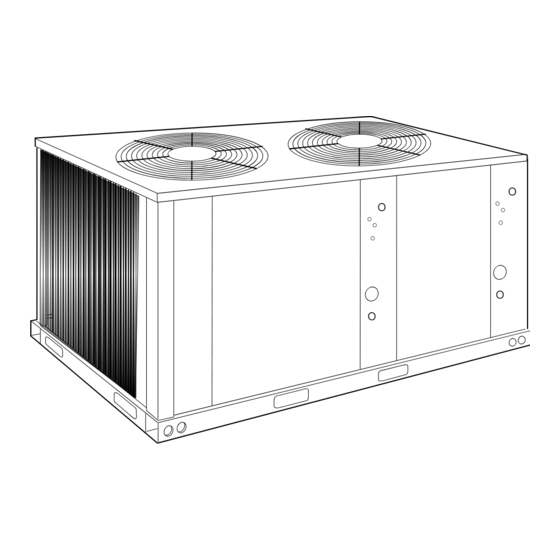
Page 9: Unit Dimensions And Clearances
Rear 24" 0" Bottom Units must be installed outdoors. Overhanging structures or shrubs should not obstruct condenser air discharge. Adequate snow clearance must be provided if winter operation is expected. FIGURE 5 - Unit Dimensions and Clearances Unitary Products Group... -
Page 10: Refrigerant Piping
The velocity of the suction gas must always be great Never solder vapor and liquid lines together. They can enough to carry oil back to the compressor. be taped together for convenience and support pur- Unitary Products Group... -
Page 11: Service Valves
Never remove a cap unless the valve is fully back- 3. Turn the stem in (or clockwise) between 1/4 and 1/ seated with its valve stem in the maximum counter- 2 turn to open the access port. Unitary Products Group... - Page 12 This warning applies to any disc being on the liquid line service valve of the outdoor unit to removed from a service valve, coil connec- the hole through the vapor disc on the indoor unit. tion, etc. Unitary Products Group...
-
Page 13: Extending The Service Ports
Turn the stem of vapor connection and the vapor piping. The vapor the liquid service valve clockwise 1/4 turn to open its line can now be brazed to the vapor connection on access port for reading pressure. Unitary Products Group... -
Page 14: Balance Point Setting
2. The building heat loss at the outdoor design tem- close their access ports after the system has been perature, and charged. 3. The heating capacity of the system at the outdoor design temperature. FIGURE 6: EXTENDING THE SERVICE PORT Unitary Products Group... -
Page 15: Alternate Charging Methods
During the heating cycle, when the reversing valve solenoids becomes energized, operation will be the solenoids becomes de-energized, compressor dis- same as any conventional air conditioning system. charge gas will be diverted to the indoor coil and the outdoor coil will become the evaporator. Unitary Products Group... -
Page 16: System Sequence Of Operation
Contactors 2M and 4M 5. The thermostat will cycle the unit to satisfy the are energized through the NO contacts on auxiliary cooling requirements of the conditioned space. contactors 1M-AUX and 3M-AUX in order to start the outdoor fan motors. Unitary Products Group... -
Page 17: Defrost Cycle
TH1 of the room thermostat if the fan switch is in the “AUTO” posi- heating operation, it must be defrosted before it blocks tion. the flow of air across the coil. Unitary Products Group... -
Page 18: Emergency Heat Operation
The rior of the unit (tools, construction or shipping compressor will run, but the reversing valve will be materials, etc.)? de-energized. Warm air will be supplied to the con- ditioned space. Unitary Products Group... -
Page 19: Safety Features
Reset the thermostat and wait 5 crankcases of the compressor during an "OFF" minutes. If the unit doesn’t start, call a serviceman. cycle. Unitary Products Group... -
Page 20: Cooling Mode Charging Chart - Ese180A Cooling Mode Charging Chart - Ese240A
035-17399-001-A-0102 FIGURE 8: COOLING MODE CHARGING CHART - ESE180A FIGURE 9: COOLING MODE CHARGING CHART - ESE240A Unitary Products Group... -
Page 21: Heating Mode Charging Chart At 4800 Cfm Ese180A
035-17399-001-A-0102 FIGURE 10: HEATING MODE CHARGING CHART AT 4800 CFM ESE180A FIGURE 11: HEATING MODE CHARGING CHART AT 6000 CFM ESE240A Unitary Products Group... -
Page 22: Heating Mode Charging Chart At 6600 Cfm Ese180A
035-17399-001-A-0102 FIGURE 12: HEATING MODE CHARGING CHART AT 6600 CFM ESE180A FIGURE 13: HEATING MODE CHARGING CHART AT 6400 CFM ESE240A Unitary Products Group... -
Page 23: Heating Mode Charging Chart At 6400 Cfm Ese240A Heating Mode Charging Chart At 7000 Cfm Ese240A
035-17399-001-A-0102 FIGURE 14: HEATING MODE CHARGING CHART AT 7000 CFM - ESE240A IDDB 80 °F 70 °F 60 °F Suction P essu r e (psi g) FIGURE 15: HEATING MODE CHARGING CHART AT 7600 CFM - ESE240A Unitary Products Group... - Page 24 Subject to change without notice. Printed in U.S.A. 035-17399-001-A-0102 Copyright © by Unitary Products Group 2002. All rights reserved. Supersedes: 035-17399-000 REV A (0601) Unitary 5005 Norman Products York Group Drive 73069...
Need help?
Do you have a question about the EASE180A25 and is the answer not in the manual?
Questions and answers