Table of Contents
Advertisement
Quick Links
I
0
AB
IJ
QR
YZ
MG 807
DB 599 (GB) 09.01
Printed in Germany
GB
Instruction Manual
On board computer
AMATRON II-A
7
8
9
CD
EF
4
5
6
KL
MN
1
2
3
ST
UV
,
=
0
Eingabe
Input
AMAZONE_WERKE
H. Dreyer GmbH & Co.KG
:
kg;l
ha
GH
km
*
h
OP
-
ha/h
1/min
WX
C
+
a
T1
T2
T3
T4
ACTION
100%
+10%
-10%
Before starting to oper-
ate,
please
carefully
read and adhere to this
instruction manual and
safety advice.
Advertisement
Table of Contents

Related Manuals for Amazone AMATRON II-A


Summary of Contents for Amazone AMATRON II-A
- Page 1 Instruction Manual On board computer AMATRON II-A AMAZONE_WERKE H. Dreyer GmbH & Co.KG kg;l ACTION ha/h 100% 1/min +10% -10% Eingabe Input Before starting to oper- MG 807 DB 599 (GB) 09.01 ate, please carefully Printed in Germany read and adhere to this instruction manual and safety advice.
- Page 2 Copyright © 2001 AMAZONEN-WERKE H. DREYER GmbH & Co. KG D-49502 Hasbergen-Gaste Germany All rights reserved AMATRON II-A DB 599 09.01...
-
Page 3: On Receipt Of The Computer
Only immediate claims to be filed with the forwarding agency may lead to re- placement. Please check whether all parts men- tioned in the following are provided. AMATRON II-A DB 599 09.01... -
Page 4: Table Of Contents
Operating sequence fertiliser spreader ZA-M .................. 23 Data block Job.......................... 23 6.1.1 Menu ‚ name / address‘....................23 6.1.2 Menu spread rate ......................23 6.1.3 Menu "Comment" ......................24 6.1.4 Menu "Implement serial number"‘ ................24 Data block machine........................25 AMATRON II-A DB 599 09.01... - Page 5 Function key and their use during the spraying operation ............49 7.5.1 Pocket calculator function....................49 7.5.2 Key: Worked part or total area..................49 7.5.3 Key: Forward speed and operational times ..............49 7.5.4 Key: Change of application rate...................50 Alarm ............................51 AMATRON II-A DB 599 09.01...
- Page 6 Fault messages and remedy ....................55 Operation of the fertiliser spreader in the event of electrical failure ............56 Operation of the field sprayer in the event of electrical failure ..........58 Determined implement data........................ 59 AMATRON II-A DB 599 09.01...
-
Page 7: Information About The Computer
Information about the computer Information about the com- puter Range of application AMATRON II-A can be coupled with the AMA- ZONE-, BBG-field sprayers and AMAZONE fertil- iser spreaders ZA-M and can be used as a display, monitoring and controlling device. -
Page 8: Designated Use Of The On Board Computer
AMAZONE spare parts. Claims regarding damage not having ocurred on All applicable accident prevention advice as well as the AMATRON II-A itself will be rejected. This also any further generally accepted safety-, working-, applies to damage due to application errors when medical- and road traffic rules should be adhered fertilising or spraying. -
Page 9: Hint Symbol
Install the transmitter spaced apart from the tractor’s electronic. When installing the antenna ensure an appropriate installation with proper earth connection between antenna and tractor earth. AMATRON II-A DB 599 09.01... -
Page 10: Description Of Product
Information about the computer Description of product Description of system The AMATRON II-A can be used as a fully automatic controlling device on fertiliser spreaders and field sprayers. The device allows an area specific spread rate control depending on the pre-set desired values and in relation to the actual forward speed and work- ing width. - Page 11 Sensor Y (operational position) (Option) holder 3 point-hydraulics basic console tractor signal distributor brown blue brown constant current socket Tractor DIN 9680 blue Implement coupling implement signal distributor, e.g. for Sensor X (wheel) field sprayer AMATRON II-A DB 599 09.01...
-
Page 12: Review
10 Cap profile rail Retainer for computer AMATRON II A and the switch box or the implement adapter. 11 Guide groove for AMATRON II-A and switch box or imple- ment adapter. 12 Clamping bolts to affix the computer and the switch box or implement adapter. -
Page 13: Fitting Instructions
If AMATRON II-A is exclusively used on a trailed field sprayer the tractor signal distributor can be dropped. The power supply is then ensured via the switch box. -
Page 14: Sensor X (Determination Of The Travelled Distance)
Screw on tachometer shaft to the free end of the adapter. Fig. 2 A tachometer adapter is available for Unimog. Dismantle tachometer shaft from the gearbox and fit the provided adapter. AMATRON II-A DB 599 09.01... -
Page 15: Sensor Y (Operational Position)
If the machine is in trans- port position the magnet should have a minimum spacing of 40 mm from the solenoid switch.. Example: Tractor three point hydraulics. Fig. 4 AMATRON II-A DB 599 09.01... -
Page 16: Tractor Signal Distributor For Tractors With Signal Socket
In addition the computer identifies the implement type via an implement specific coding. The implement relevant program and the once entered implement data are automatically selected. The implement plug also governs the machine. Two connecting variations are available. AMATRON II-A DB 599 09.01... - Page 17 (socket) switch box required when the implement is manually actuasted (e.g. field sprayer) implement plug (socket) implement adapter required when the implement is not manually actuated (e.g. single seeder) AMATRON II-A DB 599 09.01...
-
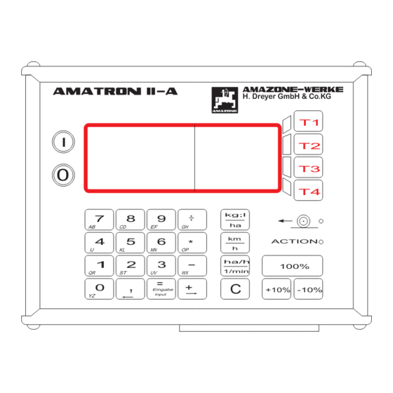
Page 18: Putting To Operation
6/1) in the first line and underneath the number of (4)/(5) Light-emitting diode. version (Fig. 6/2). Display The AMATRON II-A is provided with a 4 (lines) x 20 character alphanumerical display (Fig. 7/A). The display is divided into two fields. The l.h. field (6) 14.05.00... - Page 19 10 %-steps, related to the re- quired value. The light emitting diode (Fig. 7/E) next to the sym- bol "Action" shows the operational position, the light emitting diode (Fig. 7/D, function display travel) above must flick while travelling. AMATRON II-A DB 599 09.01...
-
Page 20: Operator Review
Putting to operation 5.1.3 Operator review 5.1.3.1 Fertiliser spreader AMATRON II-A DB 599 09.01... -
Page 21: Field Sprayer
Putting to operation 5.1.3.2 Field sprayer AMATRON II-A DB 599 09.01... -
Page 22: Data Selection
Here, all implement specific data are entered, as, e.g. working width, calibration factors, hopper content, etc. When all data inquiries have been answered, the computer automatically returns to the menu selection (please see para. 6.2 / para. 7.2). AMATRON II-A DB 599 09.01... -
Page 23: Operating Sequence Fertiliser Spreader Za-M
Following this sequence helps to avoid entering mistakes. Fig. 11 Via the 10 digit key board enter the spread rate (kg/ha) as required value (equivalent to the quan- tity which is intended to be constantly spread in AMATRON II-A DB 599 09.01... -
Page 24: Menu "Comment
"Start job?" (please see para. 6.3.1). If different implements of the same type are con- nected with AMATRON II-A (e.g. a second fertiliser • By pressing key (Next), a comment can broadcaster with different implement data), the then be filed in the data block "job"... -
Page 25: Data Block Machine
Accurately travel along the calibration distance from the starting to the ending point. With the first impulse after having started the vehicle the counter returns to "0". The determined impulses (Fig. 17/1) are shown on the display. AMATRON II-A DB 599 09.01... -
Page 26: Menu "Working Width
The fertiliser calibration factor determines the con- the range (implement, gearbox or radar) for which trolling behaviour of AMATRON II-A and depends the impulse figure is known. Enter the known figure in the data block "machine" the flowing behaviour of the fertiliser to be "impulses/100 m"... - Page 27 Fill a sufficient amount of fertiliser into the stor- Fig. 21 age hopper. • The calibration procedure can be stopped by Remove the left hand (seen in driving direction) spreading disc. pressing key (Back). AMATRON II-A DB 599 09.01...
-
Page 28: Menu Hopper Content
Operating sequence fertiliser spreader ZA-M - W e i g h t h e c o l l e c t e d f e r t i l i s e r ( c o n s i d e r n e t w e i g h t o f b u c k e t ) . -
Page 29: Data Block Operation
Fig. 29 This menu provides you with information about the entered spread rate (required value) (Fig. 29/1), a prediction about the remaining distance (m) (Fig. 29/2) and the worked area (ha) (Fig. 29/3) as well AMATRON II-A DB 599 09.01... -
Page 30: Menu "Filling The Hopper
Then the display jumps to the display for the next job (please refer to Display para. 6.1.1) Fig. 31 • By pressing key (Next) return to the ac- tual operational display. When emptying the hopper press key (hop- per empty): AMATRON II-A DB 599 09.01... -
Page 31: Data Block Memory
6.4.5). ment for the relevant job can be read out (see the following para. 6.4.4). • By pressing key (Next) the registered operational data for the relevant job can be re- called (see para. 6.4.2). AMATRON II-A DB 599 09.01... -
Page 32: Read Out The Comment
Delete memory If you select in the display for the memory space (compare 6.4.1) key (Delete), the following display appears: Fig. 40 After reading out all data memory spaces the entire memory can be deleted. AMATRON II-A DB 599 09.01... -
Page 33: Function Keys And Their Use During The Spreading Operation
Fig. 44 • By pressing key (Next you will return to the actual operational display. ha/h 1/min Via key the present (Fig. 45/1) and the aver- age (Fig. 45/2) area efficiency are displayed. Fig. 42 AMATRON II-A DB 599 09.01... -
Page 34: Key: Change Of Application Rate
-10 % By pressing key the application rate can be reduced or the pre-set value can be set again by 100 % once pressing key -10 % This also applies for key in the reverse order. AMATRON II-A DB 599 09.01... -
Page 35: Alarm
In case of missing inputs, critical implement condi- tion grave input mistakes AMATRON II-A releases a visual and audible alarm. Required value Fig. 47 The entered required rate (spread rate) cannot be maintained, because, e.g. the speed is too high. As soon as the speed has been adapted or e.g. -
Page 36: Spreading Extremely Small Spread Rates
34 kg/ha. spread rates Table 3: "Spread rate setting CAN 27% N granular BASF" – excerpt from setting chart AMATRON II-A is not suited for spreading slug pellets.! CAN 27 % gran. BASF; Hydro; DSM; Kemira; Agrolinz 1,06 kg/l CAN 27 % N gran. -
Page 37: Operating Sequence Field Sprayer
Following this sequence helps to avoid entering mistakes. Fig. 52 Via the ten digit key board enter the desired spray rate (Fig. 52/1) (equals the spray rate in l/ha to be AMATRON II-A DB 599 09.01... -
Page 38: Menu "Comment
"job" (see para. 7.1.3). If different implement of the same type are con- nected with AMATRON II-A (e.g. a second field sprayer with different implement data), the individ- 7.1.3 Menu "Comment"... -
Page 39: Data Block Machine
• With key (Back) the calibration procedure The figure "impulses/100 m" must not can be stopped. be smaller than 170. AMATRON II-A Accurately travel along the calibration distance would not operate properly. from the starting to the ending point. With the first impulse after having started the vehicle the For entering the calibration figure "Imp./100m"... -
Page 40: Menu "Working Width
By This calibration factor determines the control be- Eingabe Input haviour of AMATRON II-A and depends on the pressing key the determined value is type of field sprayer and the type of control unit. stored By pressing key (Calibrat.) a fresh cali-... -
Page 41: Tank Content
Then confirm the value by pressing key Eingabe Input Fig. 65 At random AMATRON II-A can be operated with the tank meter and the TANK-Control. Fig. 63 The computer now determined the impulses per litre and shows the calculated value (Fig. 64/1) on the display. -
Page 42: Menu "Pressure Range
Here the minimum and maximum allowed value of the pressure range (in bar) is entered. In order to monitor the spray pres- sure with AMATRON II-A the pressure range valid for the nozzles must be Fig. 70 entered (NOTE: observe the type of nozzle and the advice of the nozzle •... -
Page 43: Menu "Control Constant
, After confirmation the display automatically The following table shows the equipment of the jumps into the menu selection. different control units: Table 4: Type of control unit AMATRON II-A DB 599 09.01... -
Page 44: Data Block Operation
(see Fig. X / para. 7.3.2). • Press key (no) to reset the start proce- dure and the following display will appear: Fig. 76 The job can again be started as described above. AMATRON II-A DB 599 09.01... -
Page 45: Operational Data - Spray Rate "L/Min
• Press key (Bin) to enter data for filling or emptying the tank (see para. 7.3.5). AMATRON II-A DB 599 09.01... -
Page 46: Menu "Termination Of Job
(see follow- ing para. 7.4.2). • Press key (yes) to finish and store the job. The display will then jump into the next job display (see display Display para. 7.1.1). AMATRON II-A DB 599 09.01... -
Page 47: Display Of The Determined Values
• By pressing key (Next) the entered com- ment for the relevant job can be read out (see the following para.. 7.4.4). Fig. 90 After reading out all data memory spaces the entire memory can be deleted. AMATRON II-A DB 599 09.01... - Page 48 However, during deletion all 20 jobs are irrevocably deleted. • By pressing key (no) the deletion proce- dure is reset and the display "choice of menus" (with stopped vehicle) or the "operational dis- play" (with driving vehicle, para. 7.3.2) appears. AMATRON II-A DB 599 09.01...
-
Page 49: Function Key And Their Use During The Spraying Operation
Fig. 94 • Press key (Next) to return to the actual operational display. ha/h 1/min Via the key the present (Fig. 95/1) and the Fig. 92 average (Fig. 95/2) area efficiency are displayed. AMATRON II-A DB 599 09.01... -
Page 50: Key: Change Of Application Rate
By pressing key the total amount can be reduced or the pre-set value can be set again by 100 % once pressing key -10 % This also applies for key . in the reverse or- der. AMATRON II-A DB 599 09.01... -
Page 51: Alarm
Alarm Additional fault messages and their In case of missing inputs, critical implement condi- remedy are described in para. 9.. tion or grave input mistakes AMATRON II-A re- leases a visual and audible alarm. Required value Fig. 97 The entered required rate (spray rate) cannot be maintained, because, e.g. -
Page 52: Repair, Maintenance And Servicing
Computer Enter the working width of 20 m and store. Enter the value 1.15 for the fertiliser calibra- AMATRON II-A is maintenance free. It is provided tion factor and store. with an electronic safety device. During winter time AMATRON II-A should be stored at room tem- Execution perature. - Page 53 If necessary, slacken the pointer fixing (Fig. 102/1) and align the pointer read off edge (Fig. 102/2) on top the scale figure 41. Fig. 102 AMATRON II-A DB 599 09.01...
-
Page 54: Field Sprayer
Before starting the season, calibrate your sprayer (please refer to para. 7.2.3). For maintaining, repairing and serv- icing when operating your sprayer with the computer, please observe the instruction manual for the field sprayer. AMATRON II-A DB 599 09.01... -
Page 55: Malfunctions
After switching on the dis- The memory contents is Switch on and off computer play shows "memory error" distorted by a disturbing several times. (Speicherfehler) several pulse. languages. Claims regarding damage due to application errors will be rejected. AMATRON II-A DB 599 09.01... -
Page 56: Operation Of The Fertiliser Spreader In The Event Of Electrical Failure
Operation of the fertiliser spreader in the event of electrical failure In the event of electrical faults occurring on the com- puter AMATRON II-A or the electric setting motors, the operation can be continued even if the fault cannot be remedied straight away. - Page 57 (Fig. 107/2) as follows: Remove thumb nut (Fig. 107/3). Remove the pins and exchange (Fig. 108) the position of the two washers (Fig. 107/4) from the rear (Fig. 107/5) to the front. Fig. 107 Fig. 108 AMATRON II-A DB 599 09.01...
-
Page 58: Operation Of The Field Sprayer In The Event Of Electrical Failure
Malfunctions Operation of the field sprayer in the event of electrical failure For operating the field sprayer in the event of an electrical failure, please refer to the instruction manual for your field sprayer. AMATRON II-A DB 599 09.01... -
Page 59: Determined Implement Data
Spread rate (kg/ha) Working width (m) Field sprayer Impulses/100 m (soft soil) Impulses/100 m (medium soil) Impulses/100 m (hard soil) Working width (m) Mittelart Flow meter calibration factor (Imp./l) Spray rate (l/ha) Pressure (bar) Control constant AMATRON II-A DB 599 09.01... - Page 60 Determined implement data AMATRON II-A DB 599 09.01...
- Page 61 Notices AMATRON II-A DB 599 09.01...
- Page 62 Notices AMATRON II-A DB 599 09.01...
- Page 63 P. O. Box 51 Tel.: ++49 (0) 54 05 50 1-0 Telefax: ++49 (0) 54 05 50 11 93 D-49202 Hasbergen-Gaste e-mail: amazone@amazone.de http:// www.amazone.de Germany Branch factories at: D-27794 Hude • D-04249 Leipzig • F-57602 Forbach Subsidiaries in England and France Factories for: Fertiliser broadcasters, -storage halls, -handling systems.
Need help?
Do you have a question about the AMATRON II-A and is the answer not in the manual?
Questions and answers