
Related Manuals for Amazone Amalog


Summary of Contents for Amazone Amalog
- Page 1 Operating Instructions On-Board Computer $0$/2* Before starting to operate, MG 715 please carefully read and DB 550-1 GB 05.03 adhere to this operation Printed in Germany manual and safety advice!
- Page 2 Copyright © 2003 AMAZONEN-WERKE H. DREYER GmbH & Co. KG D-49502 Hasbergen-Gaste Germany All rights reserved...
-
Page 3: Table Of Contents
Hint symbol............................6 Safety advice for retrofitting electric and electronic devices and/or components ......6 Safety advice for repair work......................7 Description of product........................8 AMALOG with seed drills D9, AD3, RP-AD3 ...................8 AMALOG with seed drills AD-P, RP-AD-P..................8 Functions ............................8 4.3.1 Operating display ..........................9 Keypad layout..........................10... -
Page 4: On Receipt Of The Computer
On receipt of the computer, please check for transport damage or whether any parts are emitting. Only immediate claims to be filed with the forwarding agency may lead to replacement. Scope of delivery: 1. Computer 2. Console 3. Battery cable (special option NE190) AMALOG DB 550-1 05.03... -
Page 5: Information About The Computer
When ordering spare parts indicate the serial number of the AMALOG. Claims regarding damage not having occured on the AMALOG itself will be rejected. This also applies to safety requirements only damage due to sowing errors. -
Page 6: Safety
Firmly install the device. The use of portable or mobile devices inside the tractor cab is only permissible with a connection to a firmly installed external antenna. Install the transmitter spaced apart from the tractor’s electronic. AMALOG DB 550-1 05.03... -
Page 7: Safety Advice For Repair Work
Safety advice for repair work Before carrying out any repair work on the electric system or arc welding on the tractor mounted implement, disconnect all connections of AMALOG. AMALOG DB 550-1 05.03... -
Page 8: Description Of Product
[ha] and stores the finished total area [ha]. stores the finished total area [ha]. AMALOG is provided with a memory and a lithium battery. All entries and calculated values remain stored for approx. 10 years, even if the on-board power supply has been switched off. -
Page 9: Operating Display
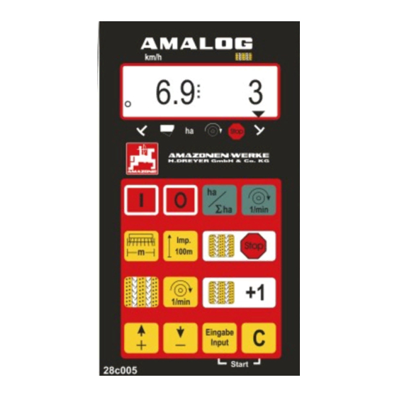
4.3.1 Operating display As soon as AMALOG receives first impulses by the sensor (hectare) the "operating display" appears. Operating display Forward speed [km/h] Position of the tramline counter Track marker "left hand side" Track marker "right hand side" in operating position... -
Page 10: Keypad Layout
Indicating or entering the ground related sensor impulses over a distance of 100 m Pressing the key prevents the automatic counting up the tramline counter Indicating or entering the current switching rhythm Entering the blower fan desired speed Switching forward the tramline counter AMALOG DB 550 05.03... - Page 11 Input key for increasing the displayed value Input key for decreasing the displayed value Key used to confirm all entries Correction key AMALOG DB 550-1 05.03...
-
Page 12: Operation
Mode "1" (free function) Operation Under mode "1" always dial the value "01". AMALOG on-/off switching By pressing key AMALOG is switched on and Press key hold and simultaneously press by pressing key it is switched off. to unlock the entering "Mode 1". -
Page 13: Mode "2" (Number Of Track Marker Sensors)
"01" or "02" to "99" on the display. Press key to store the dialled value e. g. "00" and to secure against unintended change. Seed drill with one track marker sensor on the marker change Seed drill with two track marker sensors 22t280 AMALOG DB 550-1 05.03... -
Page 14: Mode "3" (Select Implement Type)
The first figure (3) shows the chosen Mode "3", the second figure (01) the connected pneumatic seed drill. Via the keys select the coding "00" or "01" on the display. Press key to store the selected value, e.g. and to secure against unintended change. AMALOG DB 550 05.03... -
Page 15: Mode "4" (Option) (Enter The Period Of Time Between The Incidence Of A Fault And The Release Of The Alarm)
22 sec. to 10 sec. can be set. Fig. 3 Press key and store the figure. In case of a fault on the tramline kit an audible alarm sounds and the display (Fig. 4) appears. Fig. 4 AMALOG DB 550-1 05.03... -
Page 16: Mode "5" (Option) (Set The Period Of Time Until An Order Is Carried Out)
22 sec. to 10 sec. can Fig. 6 be set. Press key to store the figure. In case of a fault on the tramline kit an audible alarm sounds and the display (Fig. 7) appears. Fig. 7 AMALOG DB 550 05.03... -
Page 17: Entering The Implement Specific Data
5.2.5.1 Entering the implement specific data 5.2.5.1.1 Calibrating the distance sensor In order to enable AMALOG to determine the actual forward speed, it requires the value "Imp./100m" which the hectare sensor sends out to AMALOG when driving a previously measured and marked length of 100 m. - Page 18 Ø 1,18 drive drive 1/40 ha 27,0 59,0 27,0 59,0 22,5 49,0 22,5 49,0 17,0 37,0 17,0 37,0 15,0 33,0 15,0 33,0 Sensor- fixing on gearbox AMALOG- 1053 1175 Impulses / 100 m AMALOG DB 550 05.03...
- Page 19 AMALOG Impuls / 100m (mean value) D9 Super, D9 Special Crank- turns on the working width wheel 1/40 ha Tyres 46,0 6.00 - 16 38,5 37,0 10.0/75 - 15 28,0 37,0 31x15.5 – 15 Mitas 28,0 AMALOG DB 550-1 05.03...
- Page 20 Auf (100m). Press key and this way store the displayed, determined calibration figure (Imp./100m). Press key once again and check the stored calibration figure. The display should now show the determined calibration figure. e. g. 1005 Imp./100m. AMALOG DB 550 05.03...
-
Page 21: Enter The Working Width
3. Converting the number of crank turns 5.2.5.1.2 Enter the working width For determining the worked areas AMALOG requires Example: the information of the working width. To enable it Type of seed drill: AD-P02 enter the working width as follows: Working width: Imp./100m (actual):... -
Page 22: Programming The Tramline Rhythm
(3 m) and the tramline spacing (24 m) are mentioned side by side. Read off the control rhythm "8" (here in table 5). Press key and the display shows the actual control rhythm.. AMALOG DB 550 05.03... - Page 23 Pre-select the required control rhythm via the keys (e.g. 8) . Press key and store the pre-selected value (e.g. "8"). Thereafter the following display is shown. Display with the newly entered control rhythm control rhythms provided AMALOG are mentioned in table 5. AMALOG DB 550-1 05.03...
- Page 24 Tabelle 5: Possible tramline rhythms Control rhythm Tramline counter, controlled and displayed by the on-board computer Control rhythm Tramline counter, controlled and displayed by the on-board compouter No tramlines are created AMALOG DB 550 05.03...
-
Page 25: Start Of Operation In The Field
Advancing the tramline counter is done on seed drills • with markers via the hydraulically actuated automatic marker change over. The necessary information for advancing AMALOG receives when changing the markers over from the sensor which is coupled to the automatic marker change over. -
Page 26: Preventing Unintended Advancing Of The Tramline Counter, E. G. When The Sowing Operation Is Interrupted Or When Folding In The Track Markers
Immediately after having continued the sowing tramline counter. operation or after having folded down the track markers again press key , so that the tramline counter stops flicking in the operational display. AMALOG DB 550 05.03... -
Page 27: Function Of Keys And Their Display During The Sowing Operation
Display after one time pressing the key 5.2.6.4.2 Showing the blower fan speed (only for pneumatic seed drills) After pressing key the actual blower fan speed is shown. Display after pressing the key AMALOG DB 550-1 05.03... -
Page 28: Monitoring The Blower Fan Speed
In dependence to the pre-selected wanted speed, Press key (yellow). The pre-set nominal AMALOG monitors the blower fan drive speed. If the speed will appear on the display. nominal speed then is exceeded or undercut by more than 10 % an audible signal is released and in the Change the nominal speed accordingly via the display the black triangle above the R.P.M. - Page 29 AMALOG DB 550-1 05.03...
- Page 30 AMALOG DB 550 05.03...
- Page 32 H. DREYER GmbH & Co. KG Postfach 51 Tel.: ++49 (0) 54 05 50 1-0 Telefax: ++49 (0) 54 05 50 11 93 D-49202 Hasbergen-Gaste e-mail: amazone@amazone.de http:// www.amazone.de Germany • • D-27794 Hude D-04249 Leipzig F-57602 Forbach...
Need help?
Do you have a question about the Amalog and is the answer not in the manual?
Questions and answers