Advertisement
Quick Links
WARNINGS AND CAUTIONS
• TO AVOID FIRE, SHOCK, OR DEATH; TURN OFF POWER at circuit breaker or fuse and test that power is off before wiring!
• If you are unsure about any part of these instructions, consult an electrician.
• To be installed and/or used in accordance with appropriate electrical codes and regulations.
• Use this device with copper or copper-clad wire only.
• For indoor use only.
• SAVE THESE INSTRUCTIONS.
OVERVIEW
The Leviton
®
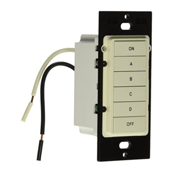
HLC Keypad Room Controller (Figure 1) allows for lighting control of a room where Leviton
UPB™ Wall Switches have been installed. It uses the UPB™ two-way powerline communication technology to
communicate with Leviton controllers, UPB™ Wall Switches, and other UPB™ devices on the network.
The HLC Keypad Room Controller has six pushbuttons labeled ON, A, B, C, D, and OFF (although these buttons
may be custom engraved). Each pushbutton is slightly backlit so that the buttons can be seen in a dark room.
Depending on configuration of the HLC Keypad Room Controller, one or more of the six pushbuttons will be
distinctly illuminated, indicating the pushbutton has been pressed or a scene has been selected. Each lighting
scene pushbutton (A-D) can be configured to custom fit an individual's lifestyle and desires. UPB™ Wall Switch
Dimmers are capable of storing preset light levels and fade rates to create powerful lighting scenes.
INSTALLATION
1. WARNING: TO AVOID FIRE, SHOCK, OR DEATH; TURN OFF POWER at circuit breaker or fuse and test
that power is off before wiring!
2. If applicable, remove the faceplate from the existing device, remove the existing device from the wall box, and
disconnect the wires from the existing device. Identify the "Line" (black) and "Neutral" (white) wires.
3. Remove 3/4" of insulation from each of the wires on the HLC Keypad Room Controller. Install the HLC Keypad
Room Controller by connecting wires per WIRING DIAGRAM (Figure 2).
4. After all connections have been made, be certain that all wire connectors are firmly attached and there is no
exposed copper.
5. Gently place the wires and HLC Keypad Room Controller into the wall box with the ON pushbutton at the top
of device. Using the supplied screws, attach the HLC Keypad Room Controller to the wall box.
6. Before installing the faceplate, restore power to the circuit for testing.
7. After testing the HLC Keypad Room Controller for proper local operation, install a Decora
HLC Keypad Room Controller.
HLC KEYPAD ROOM CONTROLLER OPERATION
The HLC Keypad Room Controller has many configurable items that can be set using the UPB™ UPStart configuration software. The following describes the operation of the HLC Keypad Room Controller in its factory default
configuration.
The HLC Keypad Room Controller has six pushbuttons labeled ON, A, B, C, D, and OFF (although these buttons may be custom engraved), which are used to control six lighting scenes. When the pushbutton labeled "ON" is
pressed, the LED behind the "ON" pushbutton is illuminated and any other is turned off. When the pushbutton labeled "OFF" is pressed, the LED behind the "OFF" pushbutton is illuminated and any other is turned off. When one of
the pushbuttons labeled "A", "B", "C", or "D" is pressed, the LED behind the respective pushbutton is illuminated and any other is turned off. No more than one pushbutton is illuminated at a time.
PUSHBUTTON OPERATION
In its factory default configuration:
• The "ON" pushbutton will brighten the UPB™ Wall Switch Dimmers to 100% at each switch's default fade rate when pressed. When the "ON" pushbutton is double-tapped, the UPB™ Wall Switch Dimmers will snap to 100%.
When pressed or double-tapped, the "ON" pushbutton will illuminate and any others are turned off. The "ON" pushbutton is also used to brighten the last lighting scene that was turned on. When the "ON" pushbutton is pressed
and held down, the UPB™ Wall Switch Dimmers will slowly brighten, and then stop brightening when the "ON" pushbutton is released.
• The "OFF" pushbutton will fade the UPB™ Wall Switch Dimmers to 0% (off) at each switch's default fade rate when pressed. When the "OFF" pushbutton is double-tapped, the UPB™ Wall Switch Dimmers will snap to 0%. When
pressed or double-tapped, the "OFF" pushbutton will illuminate and any others are turned off. The "OFF" pushbutton is also used to dim the last lighting scene that was turned on. When the "OFF" pushbutton is pressed and held
down, the UPB™ Wall Switch Dimmers will slowly dim, and then stop dimming when the "OFF" button is released.
• The "A" pushbutton will brighten the UPB™ Wall Switch Dimmers to 80% at each switch's default fade rate when pressed or double-tapped. When pressed, the "A" pushbutton will illuminate and any others are turned off.
• The "B" pushbutton will brighten the UPB™ Wall Switch Dimmers to 60% at each switch's default fade rate when pressed or double-tapped. When pressed, the "B" pushbutton will illuminate and any others are turned off.
• The "C" pushbutton will brighten the UPB™ Wall Switch Dimmers to 40% at each switch's default fade rate when pressed or double-tapped. When pressed, the "C" pushbutton will illuminate and any others are turned off.
• The "D" pushbutton will brighten the UPB™ Wall Switch Dimmers to 20% at each switch's default fade rate when pressed or double-tapped. When pressed, the "D" pushbutton will illuminate and any others are turned off.
CONFIGURING THE HLC KEYPAD ROOM CONTROLLER
The HLC Keypad Room Controller is designed to control a room of lighting using HLC Lighting Control but also has several configuration options that can be enabled or modified using the UPB™ UPStart configuration software.
OPTION
FACTORY DEFAULT
"ON" Pushbutton
On Button / Link 001
"OFF" Pushbutton
Off Button / Link 002
"A", "B", "C", and "D"
Scene Activator / Links 003,
Pushbuttons
004, 005, 006, respectively
"ON", "OFF", "A", "B", "C",
Each LED Indicator is
and "D" LED Indicators
assigned to its pushbutton's
Link ID.
Each LED Indicator is mutually
exclusive (only one LED is on
at a time).
UPB Transmission Attempts
2
UPB ID
NID = 255
UID = 080
LED Brightness
High
LED Backlighting
Enabled
CONFIGURING KEYPAD LOCKOUT FEATURE
HLC Keypad Room Controllers have a lockout feature that can be used to temporarily disable the pushbuttons so that they cannot be used to control lighting. To use the lockout feature:
STEP
OPERATION
Enable Lockout
Press and hold the "A", "B", "C", and "D" pushbuttons simultaneously for at least 3 seconds. All LED indicators are turned off and pushbuttons will no longer control lighting.
Disable Lockout
With the Lockout feature enabled, press and hold the "A", "B", "C", and "D" pushbuttons simultaneously for at least 3 seconds. The HLC Keypad Room Controller will reset and the pushbuttons will
become active and will be able to control lighting again.
CONFIGURING LIGHTING SCENES
HLC Keypad Room Controllers are designed to work with UPB™ Wall Switch Dimmers to create custom lighting scenes. Each pushbutton on the HLC Keypad Room Controller can be easily configured for new lighting scenes as
follows:
STEP
OPERATION
1
Press the pushbutton on the HLC Keypad Room Controller to activate the current scene (preset lighting level) in each of the UPB™ Wall Switch Dimmers.
2
Use the local rocker switch on each UPB™ Wall Switch Dimmer(s) to set the desired lighting level(s).
3
Press the pushbutton on the HLC Keypad Room Controller five (5) times quickly.
4
Each UPB™ Wall Switch Dimmer will flash its lighting load one time to indicate that the new level has been configured.
© 2016 Leviton Mfg. Co., Inc.
HLC KEYPAD ROOM CONTROLLER
Cat. No. HLCK6
INSTALLATION INSTRUCTIONS AND USER'S GUIDE
faceplate over the
®
1ST - 7TH UNIT IN AN HLC ROOM
Turns all lighting loads in the room on at their default fade rate.
Turns all lighting loads in the room off at their default fade rate.
Activates four different lighting scenes in the room.
When any light in the room is turned on or the "ON" pushbutton is pressed,
the "ON" pushbutton is illuminated and any other is turned off. When all lights
in the room are turned off or the "OFF" pushbutton is pressed, the "OFF"
pushbutton is illuminated and any other is turned off. When pushbutton "A",
"B", "C", or "D" is pressed, the respective pushbutton is illuminated and any
other is turned off.
No change
Leviton controller configures Network ID (NID), Unit ID (UID), Network
Password, Network Name, Room Name, Device Name, etc.
No change
No change
For Technical Assistance Call: 800-824-3005 - www.leviton.com
ON
A
B
C
D
OFF
Figure 1
HLC Keypad Room Controller
8TH UNIT IN AN HLC ROOM
Toggles the lighting loads in Room 1 on and off.
Toggles the lighting loads in Room 2 on and off.
Toggles the lighting loads in Room 3 through Room 6 on and off, respectively.
When the room is turned on using the pushbutton, the LED indicator under
the respective pushbutton is illuminated. When the room is turned off using
the pushbutton, the LED indicator under the respective pushbutton is turned
off. Anytime a lighting load in a room is turned on, the LED indicator under the
respective pushbutton (room) is illuminated. When all loads in a room are turned
off, the LED indicator under the respective pushbutton (room) is turned off.
No change
Leviton controller configures Network ID (NID), Unit ID (UID), Network
Password, Network Name, Room Name, Device Name, etc.
No change
No change
DI-000-HLCK6-00A-X2
ON
A
B
C
D
OFF
Hot (Black)
Line
120 VAC, 60Hz
Neutral (White)
Figure 2
Wiring Diagram
DI-000-HLCK6-00A-X2
ENGLISH
Advertisement

Subscribe to Our Youtube Channel
Related Manuals for Leviton HLCK6


Summary of Contents for Leviton HLCK6
- Page 1 The Leviton ® HLC Keypad Room Controller (Figure 1) allows for lighting control of a room where Leviton UPB™ Wall Switches have been installed. It uses the UPB™ two-way powerline communication technology to communicate with Leviton controllers, UPB™ Wall Switches, and other UPB™ devices on the network.
- Page 2 Leviton warrants to the original consumer purchaser and not for the benefit of anyone else that products manufactured by Leviton under the Leviton brand name (“Product”)
Need help?
Do you have a question about the HLCK6 and is the answer not in the manual?
Questions and answers