Table of Contents
Advertisement
Available languages
Available languages
Quick Links
Bedienungsanleitung
celexon Leinwand Motor
HomeCinema Plus Tension - CLR
UST
Vielen Dank für den Kauf dieses Produkts.
Für eine optimale Leistung und Sicherheit lesen Sie diese Anweisungen bitte sorgfältig
durch, bevor Sie dieses Produkt anschließen oder betreiben. Bitte bewahren Sie diese
Anleitung für eine spätere Verwendung auf.
Version: 32423_051
Advertisement
Table of Contents

Related Manuals for Celexon HomeCinema Plus Tension


Summary of Contents for Celexon HomeCinema Plus Tension
- Page 1 Bedienungsanleitung celexon Leinwand Motor HomeCinema Plus Tension - CLR Vielen Dank für den Kauf dieses Produkts. Für eine optimale Leistung und Sicherheit lesen Sie diese Anweisungen bitte sorgfältig durch, bevor Sie dieses Produkt anschließen oder betreiben. Bitte bewahren Sie diese Anleitung für eine spätere Verwendung auf.
- Page 2 Beschädigungen am Produkt zu finden sind. Sollten Sie äußerliche Beschädigungen an dem Gerät oder unerwartete oder unübliche Funktionsweisen feststellen, darf das Produkt nicht weiter genutzt werden. Kontaktieren Sie umgehend den Händler, bei dem Sie das Produkt gekauft haben oder celexon direkt (Web: www.celexon.de, Mail: info@celexon.de) für weitere Informationen. •...
- Page 3 (Web: www.celexon.de, Mail: info@celexon.de). • Technische Änderungen und Irrtümer vorbehalten. Der Hersteller übernimmt keine Verantwortung für Sachschäden oder Personenschäden, wenn die Leinwand außerhalb der empfohlenen Spezifikationen verwendet wird, oder bei unsachgemäßer Installation. Verwenden Sie diese Leinwand nicht in der Nähe von Heizungen oder Klimaanlagen.
- Page 4 WICHTIGE HINWEISE ZUR TUCHREINIGUNG UND PFLEGE Verwenden Sie keinen Lappen zur Reinigung! Dieses Tuchmaterial reagiert besonders sensibel gegenüber Berührungen mit Händen oder fettigen, feuchten Gegenständen. Dies ist der Textur bzw. Tuchoberflächenstruktur geschuldet, welche diese Hochkontrast-Ultrakurzdis- tanz Leinwand in Ihrer Funktionsweise ausmachen. Das Tuch hat eine spürbare 3D Oberflächenstruktur, welche die gebündelte Reflektion des Projektionslichtes ausschließlich aus einem steilen Winkel von unten (UST-Projektorposition) zur Betrachter-Sitzposition (Auge maximal auf...
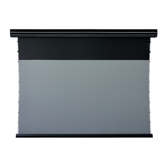
- Page 5 PRODUKTÜBERSICHT Leinwand: fl exible Montagewinkel Aluminium Gehäuse Tension Seil celexon black-grid CLR Tuch Beschwerungsstange Montagewinkel: Oberseite Obere Einhängung Verschlusselement Untere Einhängung Verschlussschraube...
-
Page 6: Technische Daten
LIEFERUMFANG 2x flexibel positionierbare 8x 5x40 mm Montage- 6x M5x10 mm Schrauben 2x Deckenabhänger für Montagewinkel Schrauben und Dübel (nur Montage an z.B. Karabinern für Beton!) 1x externer IR Empfänger 1x Adapter für Funk-Trigger 1x Infrarot-Fernbedienung 1x Inbusschlüssel Funktrigger Funktrigger (Sender) (Empfänger) TECHNISCHE DATEN... - Page 7 INSTALLATIONSHINWEIS Nehmen Sie alle Teile aus der Verpackung und vergewissern Sie sich anhand dieser Anleitung, dass alle Teile vorhanden sind. Es gibt drei verschiedene In- stallationsarten für dieses Produkt: Wandmontage, Deckenmontage oder De- ckenabhängung. Je nach Installationsumgebung können die flexiblen Montagehalterungen an verschiedenen Stellen entlang des Gehäuses angebracht werden, um die Instal- lation zu erleichtern.
- Page 8 MONTAGE AN DER WAND ODER AN DER DECKE Wählen Sie, je nach Untergrund, die passenden Schrauben für die Montage (z.B. für Holzoberflächen, für Beton oder Rigips etc.). Montieren Sie die Montagewinkel auf dem Untergrund und achten Sie da- bei darauf, dass dieser eben ist. Tipp: Ziehen Sie beim Montieren der Halterungen eine abwischbare Linie.
- Page 9 INSTALLATION DER LEINWAND Montage an Tragwerken aus Holz: Schrauben Sie die beiliegenden 5x40 mm Schrauben durch die Löcher der Winkel wie in Abb. 2 und 3 dargestellt. Montage an Tragwerken aus Beton: Zeichnen Sie die Lochpunkte mit den Winkeln an Ihrer Wand ab und bohren Löcher passend zu den beiliegenden Dübeln.
- Page 10 Achtung: Kontrollieren Sie die Anbringung der Montagewinkel auf festen Sitz, bevor Sie die Leinwand einhängen! Nutzen Sie keinen Akkuschrauber, sondern drehen die Schrauben mit der Hand ein, um ein Überdrehen zu verhindern und eine dauerhaft feste und sichere Montage zu gewährleisten. Lassen Sie sich bei Unsicherheit von einem Fachmann beraten oder die Montage von Fachleuten durchführen.
- Page 11 Um die Leinwand fest an den Halterungen zu arretieren, drehen Sie die Verschlussschrauben im Uhrzeigersinn. Dabei wandert die Leinwand lang- sam nach oben gegen die Halterung. Wenn dies auf beiden Seiten gesche- hen ist, ist die Leinwand gegen ein versehentliches Ausheben aus den Hal- terungen gesichert.
- Page 12 MONTAGE AN ABGEHANGENER DECKE Besorgen Sie sich für die abgehängte Montage der Leinwand zu Ihrem De- ckentragwerk passende Schraubhaken und ggf. Dübel. Bei Unsicherheit lassen Sie sich z.B. im Baumarkt fachmännisch beraten. Bringen Sie diese Haken an Ihrer Decke fachlich korrekt an und achten dar- auf, dass die Haken parallel zur Wand dahinter installiert werden.
- Page 13 Bringen Sie nun die Montagewinkel mit den Deckenabhängern an der Lein- wand an und achten darauf, dass die Nuten des Gehäuses mit den Befes- tigungswinkeln übereinstimmen. Ziehen Sie die Sicherungsschrauben an, um das Gehäuse in den Halterungen zu befestigen. (Abb. 16 und 17) Abbildung 16 Abbildung 17 Prüfen Sie nach Abschluss der Schritte 2 und 3, ob die Wandhalterung...
- Page 14 INBETRIEBNAHME UND BEDIENUNG ANSCHLUSS AN DIE STROMVERSORGUNG: Entfernen Sie alle Schutzfolien oder Schrauben und stellen vor erster Inbe- triebnahme sicher, dass die Beschwerungsstange frei hängt und nicht am Gehäuse festsitzt! Dies kann sonst zu irreparablen Schäden am Produkt führen. Stecken Sie den Stecker in die Steckdose, achten Sie auf die korrekte Span- nung (220-230V).
- Page 15 externes IR-Auge Trigger Abbildung 20 Stromanschluss manuelle Steuerung Abbildung 21 NUTZUNG DER INFRAROTFERNBEDIENUNG (IR) Drücken Sie “HOCH”, um die Lein- wand einzufahren. Drücken Sie “STOPP”, um die Lein- wand zu stoppen. Drücken Sie “RUNTER”, um die Lein- HOCH wand auszufahren. STOPP Drücken Sie “Micro-HOCH”, um die RUNTER...
-
Page 16: Wichtige Hinweise
WICHTIGE HINWEISE: Der Mindestabstand der IR-Fernbedienung zum Empfänger-Auge muss 50 cm betragen. Signalübertragung bis zu 8 m Distanz zwischen Sender und Empfänger auf horizontaler Linie. Halten Sie das Empfangsauge frei von Hindernissen oder nutzen das zu- sätzliche, externe IR-Auge zur Steuerung. Steuern Sie die Leinwand niemals in feuchter oder heißer Umgebung. - Page 17 IR-Empfänger in einer Position befindet, in der er das Fernbedienungssignal empfangen kann. Sollte das Signal nicht übertragen werden, prüfen Sie, ob die Batterien der Fernbedienung noch ausreichend geladen sind und dass das IR-Auge komplett in die seitliche Buchse eingesteckt ist. (Abb. 25 und 26) Bitte beachten Sie, wenn Sie den beiliegenden Funk-Trigger nutzen, kann das IR-Auge nicht mehr verwendet werden.
- Page 18 FUNKTRIGGER Sender: Programmier Button Batteriefach Kontrollleuchte Stecker Empfänger: Programmier Button Stecker Kontrollleuchte Legen Sie die im Lieferumfang befind- liche CR2430 Batterie in das Batteriefach des Senders ein. Abbildung 29 Stecken Sie den Empfänger in den IR-Eingang der Leinwand (dieser befindet sich auf der linken Seite, hinter der Klappe).
- Page 19 Stecken Sie nun den Sender in den Trigger-Port an Ihren ausgeschalteten Pro- jektor. Stellen Sie die Trigger-Funktion in Ihrem Projektor entsprechend den Herstellerangaben ein. Alternativ können Sie beiliegende apterkabel nutzen, um Projektor den 3,5 mm Klinken- anschluss auf USB zu adaptieren.
- Page 20 Garantie abgedeckt. • Um die Vorlauflänge anzupassen, können Sie bei Ihrem Fachhändel oder bei celexon direkt eine gesonderte Anleitung anfragen. Diese ist genau zu beachten. • Verändern Sie den Vorlauf NIEMALS ohne genaue Kenntnisse der Vorge- hensweise.
- Page 21 EINSTELLUNG SPANNUNG DES TENSION SEILS Wenn das Tension-Seil locker ist, was auf einen Stoß beim Transport oder eine Fehlbedienung zurückzuführen ist (Abb. 33), drehen Sie bitte den jeweils seit- lich an der Beschwerungsstange befindlichen Einstellknopf im Uhrzeigersinn, um das Seil zu spannen (Abb. 34). Wenn das Seil zu stark gespannt ist, drücken Sie bitte den Einstellknopf und drehen Sie dann den Einstellknopf gegen den Uhrzeigersinn, um die richtige Spannung einzustellen (Abb.
- Page 22 • Die Leinwand wird im Spleißverfahren hergestellt, und die Spleißlinie weist aufgrund der oberen und unteren Spannung eine gewisse Krümmung auf, die das projizierte Bild nicht beeinträchtigt, was ein normales Phänomen ist. Planlage des Tuches: • Der werksseitig eingestellte schwarze Vorlauf darf maximal um 100 mm verlängert werden, um die Planlage zu erhalten und ein Herabfallen des Tuches von der Welle zu verhindern.
- Page 23 Europe GmbH Adresse: Gutenbergstraße 2, 48282 Emsdetten, DE Produktname: celexon Leinwand Motor HomeCinema Plus Tension - CLR Produkte, die mit dem CE-Zeichen gekennzeichnet sind, entsprechen allen Anforderungen der entsprechenden EU-Direktiven. Die EU-Konformitäts- erklärung kann unter folgender Adresse heruntergeladen werden: www.celexon.de/zertifikate...
- Page 24 Operating instructions celexon screen Electric HomeCinema Plus Tension - CLR Thank you for purchasing this product. For optimum performance and safety, please read these instructions carefully before connecting or operating this product. Please retain these instructions for future reference. Version: 32423_051...
- Page 25 Contact the dealer immediately from whom you purchased the product or celexon directly (Web: www.celexon.co.uk, Mail: info@celexon.co.uk) for further information.
- Page 26 Incorrect installation or use may also invalidate the warranty. • If you are unsure about the use of the product, please contact your specialist per- sonnel, your dealer or celexon directly (Web: www.celexon.co.uk, Mail: info@celexon. co.uk). • Technical changes and errors excepted.
- Page 27 IMPORTANT NOTES ON CLOTH CLEANING AND CARE Do not use a cloth for cleaning! This fabric material is particularly sensitive to contact with hands or greasy, damp objects. This is due to the texture of the cloth surface structure, which makes this high-contrast ultra-short distance screen work.
-
Page 28: Product Overview
PRODUCT OVERVIEW Screen: Flexible mounting brackets Aluminium housing Tension rope celexon black-grid CLR fabric Weighted rod Mounting bracket: Top suspension Closure element Lower suspension Closure element... - Page 29 IN THE BOX Flexibly positionable 8x 5x40 mm mounting 6x M5x10 mm screws 2x Ceiling hangers for mounting bracket screws and dowels (only for mounting on e.g. carabiners concrete!) 1x External IR receiver 1x Adapter for Radio 1x Infra Red Remote control 1x Allen Key Trigger 1x Radio Trigger (trans-...
-
Page 30: Installation Note
INSTALLATION NOTE Take all the parts out of the packaging and use these instructions to make sure that all the parts are present. There are three different installation methods for this product: Wall-mounted, ceiling-mounted or ceiling suspension. Depending on the installation environment, the flexible mounting brackets can be placed at different locations along the enclosure to facilitate easier installa- tion. - Page 31 MOUNTING ON THE WALL OR ON THE CEILING Depending on the surface, choose the appropriate screws for the installa- tion (e.g. for wooden surfaces, concrete or plasterboard etc.). Mount the mounting brackets on the surface and make sure that they are level.
- Page 32 INSTALLATION OF THE SCREEN Mounting on supporting structures made of wood: Screw the enclosed 5x40 mm screws through the holes in the brackets as shown in figs. 2 and Mounting on concrete supporting structures: Mark the hole points on your wall with the brackets on your wall and drill holes to match the enclosed dowels.
- Page 33 Attention: Check that the mounting brackets are firmly attached, before atta- ching the screen! Do not use a cordless screwdriver, but screw in the screws by hand to prevent over tightening and to ensure a permanently firm and secure installation. If you are unsure, seek the advice of a professional or have the in- stallation carried out by specialists.
- Page 34 To lock the screen firmly to the brackets, turn the locking screws clockwi- se. This will cause the screen to move upwards against the bracket. When this has happened on both sides the screen is secured against being inad- vertently removed from the brackets. This is the only permissible way to mount the screen! (Fig.
- Page 35 MOUNTING SUSPENDED ON CEILING For the suspended installation of the screen, get screw hooks and, if neces- sary, dowels to match your ceiling structure. If you are unsure, ask for pro- fessional advice, e.g. at a DIY store. Attach these hooks to your ceiling correctly and make sure that the hooks are parallel to the wall.
- Page 36 Now attach the mounting brackets with the ceiling hangers to the screen, making sure that the grooves of the housing match the mounting brackets. Tighten the locking screws, to secure the enclosure in the brackets. (Fig. 16 and 17) Fig. 16 Fig.
- Page 37 START-UP AND OPERATION CONNECTION TO THE POWER SUPPLY: Remove any protective film or screws and make sure that the weighted rod is hanging freely and is not stuck to the housing! This can otherwise lead to irreparable damage to the product. Insert the plug into the socket and ensure that the voltage is correct (220- 230V).
- Page 38 External IR Eye Trigger Fig. 20 Power connection Manual switch Fig. 21 USE OF THE INFRARED REMOTE CONTROL (IR) Press „UP“ to retract the screen. Press „STOP“ to stop the screen. Press „DOWN“ to extend the screen. Press „Micro-HIGH“ to raise the screen minimally (150 ms for each movement).
-
Page 39: Important Notes
IMPORTANT NOTES: The minimum distance between the IR remote control and the receiver eye must be 50 cm. Signal transmission up to 8 m distance between transmitter and receiver on a horizontal line. Keep the receiving eye free of obstacles or use the additional external IR eye for control. - Page 40 te control signal. If the signal is not being transmitted, check that the batteries in the remote control are still sufficiently charged and that the IR eye is completely plugged into the socket on the side. (fig. 25 and 26) Please note that if you use the enclosed radio trigger, the IR eye can no longer be used.
- Page 41 RADIO TRIGGER Transmitter: Programming button Battery compartment Indicator light Plug Receiver: Programming button Plug Control light Insert the CR2430 battery supplied in the battery compartment of the transmitter. Fig. 29 Plug the receiver into the IR input of the screen (this is on the left side, behind the flap).
- Page 42 Now plug the transmitter into the trigger port on your switched-off projector. Set the trigger function in your projector according to the manufacturer‘s ins- tructions. Alternatively, you can use the enclo- sed adapter cable to adapt the 3.5 mm jack Projektor connection to USB.
- Page 43 • In order to adjust the feed length, you can ask your specialist dealer or celexon directly for separate instructions. These instructions must be fol- lowed exactly. • NEVER change the advance length without precise knowledge of the procedure.
- Page 44 ADJUSTMENT OF THE TENSION ROPE If the tension rope is loose, which can be traced back to a shock during trans- port or an incorrect operation (Fig. 33), please turn the adjustment knob on the side of the weighted bar clockwise to tighten the rope (Fig. 34). If the rope is too taut, press the adjustment knob and then turn the adjustment knob an- ti-clockwise to adjust the clockwise to set the correct tension (Fig.
- Page 45 • The screen is produced by the splicing process and the splice line has some curvature due to the upper and lower tension, which does not affect the projected image and is a normal phenomenon. Flatness of the fabric: • The factory-set black drop may be extended by a maximum of 100 mm in order to maintain the flatness and prevent the fabric from falling off the shaft.
- Page 46 Gutenbergstraße 2, 48282 Emsdetten, DE Product name: celexon screen Electric HomeCinema Plus Tension - CLR Products that are marked with the CE mark meet all requirements of the relevant EU directives. The EU declaration of conformity can be downloaded from the following address: www.celexon.de/zertifikate...
- Page 47 Adress: Gutenbergstraße 2, 48282 Emsdetten, DE Product name: celexon screen Electric HomeCinema Plus Tension - CLR Products that are marked with the UKCA mark meet all requirements of the relevant UK directives. The UK declaration of conformity can be downloaded from the following address: www.celexon.de/zertifikate...
- Page 48 Notice d’utilisation Écran de projection celexon motorisé HomeCinema Plus Tension – CLR UST Merci d’avoir choisi ce produit. Pour une performance et une sécurité optimales, veuillez lire attentivement les présentes instructions avant de connecter ou d’utiliser ce produit. Veuillez conserver la présente notice pour une consultation ultérieure.
- Page 49 Si vous constatez des dommages extérieurs sur l’appareil ou des fonc- tionnements inattendus ou inhabituels, cessez d’utiliser le produit. Contactez immé- diatement le revendeur auprès duquel vous avez acheté le produit ou directement celexon (web : www.celexon.fr, mail : info@celexon.fr) pour de plus amples informa- tions. •...
-
Page 50: Exclusion De Responsabilité
Une installation ou une utilisation incorrecte peut entraîner l’annulation de la garantie. • Si vous n’êtes pas sûr lors de l’utilisation du produit, contactez le person- nel spécialisé, votre revendeur ou directement celexon (Web : www.celexon.fr, Mail : info@celexon.fr). • Sous réserve de modifications techniques et d’erreurs. - Page 51 REMARQUES IMPORTANTES CONCERNANT LE NETTOYAGE DE LA TOILE ET SON ENTRETIEN N’utilisez pas de chiffon pour le nettoyage ! La matière de cette toile est particulièrement sensible au contact des mains ou d’objets gras et humides. Cela est dû à la texture et/ou à...
- Page 52 APERÇU DU PRODUIT Écran : Équerre de montage flexible Boîtier en aluminium Câble de tension Toile celexon black-grid CLR Tige de lestage Équerre de montage : Face supérieure Suspension supérieure Élément de fermeture Suspension inférieure Vis de fermeture...
-
Page 53: Contenu De La Livraison
CONTENU DE LA LIVRAISON 2x équerre de montage à 8x vis et chevilles de 6x vis M5x10 mm 2x suspension de plafond positionnement flexible montage 5x40 mm (pour le pour montage sur mous- béton uniquement !) quetons par exemple 1x récepteur RF externe 1x adaptateur pour trigger 1x télécommande infra- 1x clé... - Page 54 CONSIGNE D’INSTALLATION Retirez toutes les pièces de l’emballage et assurez-vous, à l’aide des présentes instructions, que toutes les pièces sont présentes. Ce produit peut être installé de trois façons différentes : montage mural, montage au plafond ou suspen- sion au plafond. En fonction de l’environnement d’installation, les supports de montage flexibles peuvent être placés à...
- Page 55 MONTAGE SUR LE MUR OU AU PLAFOND Choisissez les vis appropriées pour le montage en fonction du support (par exemple pour les surfaces en bois, pour le béton ou le placoplâtre, etc.). Montez les équerres de montage sur le support en veillant à ce qu’il soit parfaitement plan.
-
Page 56: Installation De L'écran
INSTALLATION DE L’ÉCRAN Montage sur des structures porteuses en bois : vissez les vis fournies 5x40 mm dans les trous des équerres, tel qu’indiqué dans les figures 2 et 3. Montage sur des structures porteuses en béton : tracez les points de per- çage à... - Page 57 Attention : vérifiez que les équerres de montage sont bien fixées avant de suspendre l’écran ! N’utilisez pas de visseuse sans fil ; vissez les vis à la main, afin d’éviter de les serrer trop fort et garantir ainsi un montage durablement solide et sûr.
- Page 58 Pour bloquer fermement l’écran sur les supports, vissez les vis de ferme- ture dans le sens horaire. L’écran se déplace alors lentement vers le haut, contre le support. Une fois que cela a été fait des deux côtés, l’écran est sécurisé...
- Page 59 MONTAGE SUR UN FAUX PLAFOND Pour le montage en suspension de l’écran, procurez-vous des crochets à visser adaptés à votre structure porteuse de plafond ainsi que des chevilles si nécessaire. En cas de doute, demandez conseil à un professionnel (dans un magasin de bricolage par exemple).
- Page 60 Fixez maintenant les équerres de montage sur l’écran à l’aide des suspen- sions de plafond ; ce faisant, assurez-vous que les rainures du boîtier sont alignées avec les équerres de fixation. Serrez les vis de blocage pour fixer le boîtier dans les supports. (Figures 16 et 17) Figure 16 Figure 17 Une fois les étapes 2 et 3 terminées, vérifiez que le support mural est...
- Page 61 MISE EN SERVICE ET UTILISATION RACCORDEMENT À L’ALIMENTATION ÉLECTRIQUE : Retirez tous les films de protection ou les vis. Avant la première mise en service, assurez-vous que la tige de lestage pend librement et n’est pas bloquée sur le boîtier ! Cela pourrait entraîner des dommages irrémé- diables sur le produit.
- Page 62 Œil IR externe Déclencheur Figure 20 Branchement électrique Commande manuelle Figure 21 UTILISATION DE LA TÉLÉCOMMANDE INFRAROUGE (IR) Appuyez sur « HAUT » pour faire rentrer l’écran. Appuyez sur « STOP » pour stopper l’écran. Appuyez sur « BAS » pour faire sor- HAUT tir l’écran.
- Page 63 REMARQUES IMPORTANTES : La distance minimale entre la télécommande IR et l’œil du récepteur doit être de 50 cm. Transmission du signal jusqu’à 8 m de distance entre l’émetteur et le récep- teur sur un plan horizontal. Gardez l’œil de réception libre de tout obstacle ou utilisez l’œil IR externe supplémentaire.
- Page 64 le signal de la télécommande. Si le signal n’est pas transmis, vérifiez que les piles de la télécommande sont encore suffisamment chargées et que l’œil IR est complètement inséré dans la prise latérale. (Fig. 25 et 26) Attention : si vous utilisez le déclencheur RF fourni, l’œil IR ne peut plus être utilisé.
- Page 65 DÉCLENCHEUR RF Émetteur : Bouton de programma- tion Compartiment à piles Témoin lumi- neux Fiche Récepteur : Bouton de programmation Fiche Témoin lumi- neux Insérez la pile CR2430 fournie dans le compartiment à piles de l’émetteur. Figure 29 Branchez le récepteur dans l’entrée IR de l’écran (à gauche, derrière le clapet). Veuillez noter que vous ne pouvez pas utiliser le déclencheur en parallèle avec l’œil IR externe.
- Page 66 Insérez maintenant l’émetteur dans le port du déclencheur de votre projecteur éteint. Réglez la fonction de déclenchement de votre projecteur, conformé- ment aux instructions du fabricant. Vous pou- vez également utiliser câble adaptateur Projecteur fourni pour adapter la prise jack 3,5 mm à...
- Page 67 • Pour ajuster la longueur d’avance, vous pouvez demander des instruc- tions à votre revendeur ou directement à celexon. Celle-ci doit être scru- puleusement respectée. • Ne modifiez JAMAIS l’avance sans connaître précisément la procédure.
- Page 68 RÉGLAGE DE LA TENSION DU CÂBLE DE TENSION Si, à la suite d’un choc lors du transport ou d’une mauvaise manipulation, le câble de tension est lâche (Fig. 33), tournez le bouton de réglage situé sur le côté de la tige de lestage dans le sens horaire pour retendre le câble (Fig. 34). Si le câble est trop tendu, appuyez sur le bouton de réglage, puis tournez le bouton de réglage dans le sens antihoraire pour ajuster la tension (Fig.
- Page 69 • L’écran est fabriqué par épissure et la ligne d’épissure présente une cer- taine courbure due à la tension supérieure et inférieure, qui n’affecte pas l’image projetée, ce qui est un phénomène normal. Planéité de la toile : • L’avance noire réglée en usine ne doit pas être prolongée de plus de 100 mm, afin de préserver la planéité...
- Page 70 INFORMATION CONCERNANT LA CONFORMITÉ EUROPÉENNE Fabricant : celexon Europe GmbH Adresse : Gutenbergstraße 2, 48282 Emsdetten, DE Nom du produit : Écran de projection celexon motorisé HomeCinema Plus Tension – CLR UST produits comportent marque respectent toutes exigences directives européennes applicables.
- Page 71 Manual de instrucciones Pantalla motorizada tensionada HomeCinema Plus - CLR UST celexon Gracias por adquirir este producto. Para un rendimiento y seguridad óptimos, lea atentamente estas instrucciones antes de conectar o utilizar este producto. Conserve estas instrucciones para futuras consultas.
- Page 72 Si observa algún daño externo en el dispositivo o un funcionamiento inespe- rado o inusual, deje de utilizar el producto. Póngase en contacto inmediatamente con el distribuidor al que compró el producto o directamente con celexon (web: www.celexon.es correo: info@celexon.es) para obtener más información.
-
Page 73: Exención De Responsabilidad
• Si no está seguro de cómo utilizar el producto, póngase en contacto con personal cualificado, con su distribuidor o directamente con celexon (web: www.celexon.es correo: info@celexon.es). • Salvo cambios técnicos y errores. - Page 74 NOTAS IMPORTANTES SOBRE LA LIMPIEZA Y EL CUIDADO DEL TEJIDO No utilice ningún paño para la limpieza. Este material textil es especialmente sensible al contacto con las manos o con obje- tos grasientos y húmedos. Esto se debe a la textura o estructura superficial del tejido que hace funcionar esta pantalla de alto contraste y ultracorta distancia.
- Page 75 RESUMEN DEL PRODUCTO Pantalla: Ángulo de montaje flexible Carcasa de aluminio Cable de ten- sado Tejido black-grid CLR celexon Barra de lastre Ángulo de montaje: Parte superior Enganche superior Elemento de fijación Enganche inferior Tornillo de bloqueo...
-
Page 76: Datos Técnicos
VOLUMEN DE SUMINISTRO 2x ángulos de montaje de 8x 5x40 mm tornillos 6x tornillos M5x10 mm 2x suspensiones de techo de montaje y tacos (solo para el montaje en, p. ej., colocación flexible para hormigón) mosquetones 1x receptor IR externo 1x adaptador para control 1x mando a distancia por 1x llave Allen... - Page 77 NOTA DE INSTALACIÓN Extraiga todas las piezas del embalaje y asegúrese de estén todas incluidas tomando como referencia este manual. Existen tres distintos tipos de instala- ción para este producto: Montaje en pared, montaje en techo o suspensión en techo. En función del entorno de la instalación, puede instalar los soportes de mon- taje flexibles en distintos puntos de la carcasa para facilitar la instalación.
- Page 78 MONTAJE EN LA PARED O EN EL TECHO Escoja, en función de la superficie de fijación, los tornillos adecuados para el montaje (p. ej., para superficies de madera, de hormigón o de pladur, etc.). Monte el ángulo de montaje en la superficie de montaje y asegúrese de que quede nivelado.
-
Page 79: Instalación De La Pantalla
INSTALACIÓN DE LA PANTALLA Montaje en estructuras portantes de madera: atornille los tornillos 5x40 mm incluidos en los orificios del ángulo como se representa en las figuras 2 y 3. Montaje en estructuras de hormigón: marque los puntos de perforación con los ángulos colocados en la pared y perfore orificios acordes a los tacos suministrados. - Page 80 Atención: compruebe que el ángulo de montaje esté bien montado antes de colgar la pantalla. No utilice atornilladores eléctricos; en su lugar, apriete los tornillos manualmente para evitar que se pasen de rosca y garantizar un mon- taje seguro y firme. En caso de dudas, pida asesoramiento a un especialista o encargue el montaje a un servicio técnico.
- Page 81 Para fijar permanentemente la pantalla a los soportes, gire los tornillos de bloqueo en sentido horario. Así, la pantalla se desplazará lentamente hacia arriba contra el soporte. Cuando este paso se haya realizado para los dos lados, la pantalla estará asegurada contra un desmontaje accidental de los soportes.
- Page 82 MONTAJE EN FALSOS TECHOS Provéase de las alcayatas y tacos adecuados para el montaje suspendido de la pantalla en su estructura portante de techo. En caso de dudas, pida asesoramiento especializado en su tienda de bricolaje. Instale las alcayatas en el techo de manera adecuada y asegúrese de que estas estén posicionadas de manera paralela a la pared.
- Page 83 A continuación, instale el ángulo de montaje con los soportes para techo a la pantalla y asegúrese de que las ranuras de la carcasa coincidan con los ángulos de fijación. Apriete los tornillos de seguridad para fijar la carcasa en los soportes. (Fig. 16 y 17) Figura 16 Figura 17 Tras finalizar los pasos 2 y 3, compruebe que el soporte de pared esté...
- Page 84 PUESTA EN SERVICIO Y CONTROL CONEXIÓN A LA ALIMENTACIÓN ELÉCTRICA: Retire todas las láminas de protección o tornillos y asegúrese, antes de la primera puesta en marcha, de que la barra de lastre esté colgando libre- mente y no esté enganchada en la carcasa. De lo contrario, esto podría ocasionar daños irreparables en el producto.
- Page 85 Receptor externo de infrarrojos Control por radiofrecuencia Figura 20 Conexión eléctrica Control manual Figura 21 UTILIZACIÓN DEL MANDO A DISTANCIA POR INFRARROJOS (IR) Presione "ARRIBA" para subir la pantalla. Presione "PARADA" para detener la pantalla. Presione "ABAJO" para bajar la ARRIBA pantalla.
-
Page 86: Nota Importante
NOTA IMPORTANTE: La distancia mínima del mando a distancia de IR para el receptor es de 50 cm. Transmisión de la señal de hasta 8 m de distancia entre el emisor y el re- ceptor en línea horizontal. Mantenga el receptor sin obstáculos o utilice el receptor externo de IR adicional para el control. - Page 87 reciba la señal del mando a distancia. Si no se transfiere la señal, compruebe si las baterías del mando a distancia tienen suficiente carga y que el receptor de IR esté completamente encajado en la toma lateral. (Fig. 25 y 26) Tenga en cuenta que, si utiliza el control por radiofrecuencia suministrado, ya no podrá...
- Page 88 CONTROL POR RADIOFRECUENCIA Emisor: Botón programable Compartimento de las baterías Luz de control Conector Receptor: Botón programable Conector Luz de control Introduzca la batería CR2430 suministra- da en el compartimento de la batería del emisor. Figura 29 Conecte el emisor a la entrada IR de la pantalla (situada en el lado izquierdo, detrás de la solapa).
- Page 89 Ahora conecte el emisor del puerto del control por radiofrecuencia al pro- yector apagado. Configure la función de control por radiofrecuencia en su proyector siguiendo instrucciones fabricante. Como alter- nativa, puede utilizar el Proyector cable adaptador sumi- nistrado para adaptar la clavija de 3,5 mm a USB.
- Page 90 • Para ajustar la longitud del borde, consulte a su distribuidor especiali- zado o directamente a celexon para obtener instrucciones específicas. Estas deben seguirse exactamente. • No modifique NUNCA el borde sin tener conocimientos precisos del pro- ceso.
- Page 91 AJUSTE DE LA TENSIÓN DEL CABLE TENSOR Si el cable tensor está flojo, que puede deberse a un impacto durante el trans- porte o a una manipulación inadecuada (fig. 33), gire en sentido horario el botón de ajuste situado en la barra de lastre para tensar el cable (fig. 34). Si el cable está...
- Page 92 • La pantalla se fabrica por empalme y la línea de empalme presenta cierta curvatura debido a la tensión superior e inferior, que no afecta a la imagen proyectada, lo cual es un fenómeno normal. Planitud del tejido: • El borde negro ajustado de fábrica puede alargarse como máximo 100 mm para mantener la planitud y evitar una caída del tejido del eje.
- Page 93 Los productos que llevan la marca CE cumplen todos los requisitos de las direc- tivas comunitarias pertinentes. La declaración de conformidad de la UE puede descargarse en la siguiente dirección: www.celexon.de/zertifikate El símbolo hace referencia a la recogida selectiva de dispositivos eléctricos y electrónicos en los países de la UE.
- Page 94 Manuale di istruzioni Schermo di proiezione a motore celexon HomeCinema Plus Tension - CLR UST Grazie per aver acquistato questo prodotto. Per garantire prestazioni e sicurezza ottimali, leggere attentamente le presenti istruzioni prima di collegare o utilizzare lo schermo di proiezione Conservare queste istruzioni per riferimenti futuri.
- Page 95 Contattare immediatamente il rivenditore presso il quale è stato acqui- stato il prodotto o contattare direttamente celexon (sito: www.celexon.it, e-mail: info@celexon.it) per ulteriori informazioni.
-
Page 96: Esclusione Di Responsabilità
(sito: www.celexon.it, e-mail: info@celexon.it). • Con riserva di modifiche tecniche e salvo errori di stampa. Il produttore non si assume alcuna responsabilità per lesioni fisiche o danni materiali se lo schermo viene utilizzato in modo diverso dalle specifiche raccomandate, oppure se non è... - Page 97 INDICAZIONI IMPORTANTI SULLA PULIZIA E LA CURA DEL TESSU- TO DELLO SCHERMO Non utilizzare un panno per la pulizia! Questo tessuto è particolarmente sensibile al contatto con le mani o con oggetti grassi e umidi. Ciò è dovuto al tessuto ovvero alla struttura superficiale del tessuto che caratterizza la funzionalità...
-
Page 98: Panoramica Del Prodotto
PANORAMICA DEL PRODOTTO Schermo: Staffe per il montaggio flessibile Alloggiamento di alluminio Tensione della corda Tessuto celexon black-grid CLR Contrappeso Staffa di montaggio: Lato superiore Ganci superiori Elemento di bloccaggio Ganci inferiori Tappo a vite... -
Page 99: Contenuto Della Fornitura
CONTENUTO DELLA FORNITURA 2 staffe per il montaggio 8 viti di montaggio 6 viti M5x10 mm 2 ganci da soffitto per il flessibile 5x40 mm e tasselli (solo montaggio ad es. su mo- per calcestruzzo!) schettoni 1 ricevitore IR esterno 1 adattatore per radio 1 telecomando a infrarossi 1 chiave a brugola... -
Page 100: Istruzioni Di Montaggio
ISTRUZIONI DI MONTAGGIO Prelevare tutte le parti dall’imballaggio e, con l’ausilio di questo manuale, ac- certarsi che tutte le parti state inserite. Ci sono diversi tipi di montaggio per questo schermo: montaggio a parete, montaggio al soffitto, e aggancio al sof- fitto A seconda del locale di installazione, le staffe per il montaggio flessibile pos- sono essere fissate in vari punti della struttura per facilitare l’installazione. - Page 101 MONTAGGIO A PARETE O AL SOFFITTO In base alla struttura della parete o del soffitto, scegliere le viti adeguate al montaggio (ad es. per il legno, il cemento, il cartongesso, ecc.). Montare le staffe sulla parete/soffitto, assicurandosi che sia perfettamente orizzontale.
- Page 102 MONTAGGIO DELLO SCHERMO Montaggio sul legno Avvitare le viti 5x40 mm in dotazione attraverso i fori delle staffe, come mostrato nelle figure 2 e 3. Montaggio sul calcestruzzo: Segnare i fori sulla parete con le staffe e pra- ticare i fori in base ai tasselli in dotazione. I tasselli devono essere inseriti con forza nei fori.
- Page 103 Attenzione: Controllare che le staffe siano fissate saldamente prima di appen- dere lo schermo! Non utilizzare un avvitatore a batteria, avvitare le viti a mano per evitare un serraggio eccessivo e per ottenere un’installazione stabile e si- cura. In caso di incertezze, rivolgersi a uno specialista o far eseguire l’installa- zione a dei professionisti.
- Page 104 Per fissare saldamente lo schermo alle staffe, ruotare le viti di bloccag- gio in senso orario. Lo schermo si sposta lentamente verso l’alto contro la staffa. Una volta eseguita questa operazione su entrambi i lati, lo schermo è protetto contro il sollevamento accidentale dalle staffe. Questo è il solo metodo di montaggio consentito! (Fig.
- Page 105 MONTAGGIO CON AGGANCIO AL SOFFITTO Procurarsi i ganci a vite adatti e, se necessario, i tasselli per il montaggio sospeso dello schermo al soffitto. In caso di incertezze, rivolgersi a uno specialista ad es. in un negozio di materiale per il fai-da-te. Montare questi ganci al soffitto in modo corretto, accertandosi che i ganci siano installati parallelamente alla parete retrostante.
- Page 106 Fissare lo schermo alle staffe con ganci a soffitto e si assicurarsi che le scanalature dell’alloggiamento si inseriscano nelle staffe. Avvitare le viti di bloccaggio per fissare l’alloggiamento nelle staffe. (Fig. 16 e 17) Figura 16 Figura 17 Dopo aver completato i passaggi 2 e 3, controllare che le staffe siano sal- damente fissate all’alloggiamento dello schermo prima di appendere lo schermo.
- Page 107 MESSA IN FUNZIONE E FUNZIONAMENTO COLLEGAMENTO ALL’ALIMENTAZIONE ELETTRICA: Rimuovere tutte le pellicole protettive o le viti e assicurarsi che il contrap- peso penda liberamente e non sia attaccato all’alloggiamento prima della messa in funzione! In caso contrario, lo schermo potrebbe subire danni irreparabili.
- Page 108 Occhio IR esterno Trigger Figura 20 Collegamento di alimentazione Controllo manuale Figura 21 UTILIZZO DEL TELECOMANDO A INFRAROSSI (IR) Premere “SÙ” per avvolgere lo schermo. Premere “STOP” per fermare lo schermo. Premere “GIÙ” svolgere schermo. STOP Premere “Micro-SU” per sollevare lo GIÙ...
-
Page 109: Istruzioni Importanti
ISTRUZIONI IMPORTANTI: La distanza minima tra il telecomando IR e l’occhio del ricevitore deve essere di 50 cm. Trasmissione del segnale fino a 8 m di distanza tra trasmettitore e ricevito- re su una linea orizzontale. Mantenere l’occhio ricevente sempre libero da ostacoli o utilizzare l’occhio IR esterno aggiuntivo per il controllo. - Page 110 posizione idonea a ricevere il segnale del telecomando. Se il segnale non viene trasmesso, controllare che le batterie del telecomando siano ancora sufficientemente cariche e che l’occhio IR sia completamente in- serito nella presa laterale. (Fig. 25 e 26) Da notare che quando si utilizza il radio trigger in dotazione, l’occhio IR non può...
- Page 111 RADIO TRIGGER Trasmettitore: Tasto di programmazione Vano batteria: Luce di controllo Connettore Ricevitore: Tasto di programmazione Connettore Luce di con- trollo Inserire la batteria CR2430 inclusa nella fornitura nel vano batteria del trasmetti- tore. Figura 29 Collegare il ricevitore all’ingresso IR dello schermo (si trova sul lato sinistro, dietro il coperchio).
- Page 112 Collegare il trasmettitore alla porta di attivazione del proiettore spento. Im- postate la funzione trigger nel proiettore secondo le istruzioni del produttore. In alternativa, è pos- sibile utilizzare il cavo adattatore in dotazione per adattare la connes- Proiettore sione jack da 3,5 mm all’USB.
- Page 113 • Per regolare la lunghezza della mascheratura, si possono richiedere istru- zioni separate al rivenditore specializzato o direttamente a celexon. Os- servare queste scrupolosamente queste istruzioni. • Non modificare MAI la mascheratura senza una conoscenza precisa della procedura.
- Page 114 IMPOSTAZIONE DELLA TENSIONE DELLA CORDA Se la corda è allentata, a causa di un urto durante il trasporto o di un funzio- namento errato (Fig. 33), ruotare la manopola di regolazione, posta sul lato del contrappeso, in senso orario per tendere la corda (Fig. 34). Se la corda è troppo tesa, premere la manopola di regolazione e poi ruotare la manopola di regolazione in senso antiorario per impostare la tensione corretta (Fig.
- Page 115 • Lo schermo è realizzato mediante giunzione e la linea di giunzione presen- ta una certa curvatura dovuta alla tensione superiore e inferiore, che non influisce sull’immagine proiettata; si tratta di un fenomeno normale. Planarità del tessuto: • La mascheratura nera impostata in fabbrica può essere allungata di un massimo di 100 mm per mantenere la planarità...
- Page 116 Denominazione del prodotto: Schermo di proiezione a motore celexon HomeCinema Plus Tension - CLR UST I prodotti etichettati con il marchio CE soddisfano tutti i requisiti delle direttive UE vigenti. La dichiarazione di conformità UE può essere scaricata dal seguente indirizzo: www.celexon.de/zertifikate...
- Page 117 Instrukcja obsługi Ekran projekcyjny z napędem silnikowym celexon HomeCinema Plus Tension - CLR UST Dziękujemy za zakup produktu. Aby zapewnić optymalne działanie i bezpieczeństwo, przed podłączeniem lub obsługą tego produktu należy uważnie przeczytać niniejszą instrukcję. Prosimy o zachowanie niniejszej instrukcji do wykorzystania w przyszłości.
-
Page 118: Wskazówki Ostrzegawcze
Jeśli widoczne są zewnętrzne uszkodzenia urządzenia lub w przypadku stwierdzenia niespodziewanego lub nietypowego sposobu działa- nia nie wolno dalej używać produktu. Należy bezzwłocznie skontaktować się ze sprzedawcą, u którego nabyto produkt lub bezpośrednio z firmą celexon (Internet: www.celexon.pl, e-mail: info@celexon.pl), aby uzyskać więcej informacji. •... -
Page 119: Wyłączenie Odpowiedzialności
• Jeśli nie ma pewności w odniesieniu do korzystania z produktu, skontaktować się z wykwalifikowanym personelem, sprzedawcą lub bezpośrednio z firmą celexon (In- ternet: www.celexon.pl, e-mail: info@celexon.pl). • Zastrzega się możliwość zmian technicznych i błędów. Producent nie ponosi odpowiedzialności za szkody materialne lub obrażenia ciała, jeśli ekran projekcyjny będzie używany niezgodnie z zalecanymi specyfikacjami lub jeśli jest... - Page 120 WAŻNE WSKAZÓWKI DOTYCZĄCE CZYSZCZENIA I PIELĘGNACJI TKANINY Nie używać szmatki do czyszczenia! materiał tekstylny jest szczególnie wrażliwy dotyk ręka- mi lub tłustymi, wilgotnymi przedmiotami. Wynika to z tekstury lub struktury powierzchni tkaniny, która składa się na ten wysokokontrastowy ekran o ultrakrótkim zasięgu w swojej funkcjonalności. Tkanina ma zauważalną...
-
Page 121: Przegląd Produktu
PRZEGLĄD PRODUKTU Ekran projekcyjny: elastyczny kątownik montażowy obudowa aluminiowa linka napinająca tkanina celexon black-grid CLR drążek obciążający Kątownik montażowy: strona górna zaczep górny element zamykający zaczep dolny śruba zamykająca... -
Page 122: Zakres Dostawy
ZAKRES DOSTAWY 2 elastycznie ustawiane ką- 8 śrub montażowych 6 śrub M5x10 mm 2 uchwyty sufitowe do towniki montażowe 5x40 mm montażu np. na karabiń- i kołków (tylko do betonu!) czykach 1 zewnętrzny odbiornik 1 adapter do wyzwalacza 1 pilot zdalnego sterowania 1 klucz imbusowy podczerwieni IR bezprzewodowego... - Page 123 WSKAZÓWKA DOTYCZĄCA INSTALACJI Wyjąć wszystkie części z opakowania i upewnić się na podstawie tej instrukcji, że wszystkie części są. Dla tego produktu są trzy różne rodzaje instalacji: mon- taż naścienny, montaż sufitowy lub zawieszenie na suficie. W zależności od miejsca instalacji można w różnych miejscach wzdłuż obudo- wy zamocować...
- Page 124 MONTAŻ NA ŚCIANIE LUB NA SUFICIE Wybrać pasujące śruby do montażu w zależności od podłoża (np. do po- wierzchni drewnianej, do betonu lub płyt g-k itp.). Zamontować kątowniki montażowe na podłożu, zwracając uwagę, aby było ono płaskie. Wskazówka: Podczas montowania uchwytów narysować zmywalną linię (patrz rys.
- Page 125 INSTALACJA EKRANU PROJEKCYJNEGO Montaż na konstrukcjach nośnych z drewna: Przykręcić dołączone śruby 5x40 mm przez otwory kątowników, jak pokazano na rys. 2 i 3. Montaż na konstrukcjach nośnych z betonu: Narysować punkty otworów przy użyciu kątowników na ścianie i wywiercić otwory pasujące do dołą- czonych kołków.
- Page 126 Uwaga: Przed zawieszeniem ekranu projekcyjnego sprawdzić zamocowanie kątowników montażowych pod kątem dobrego osadzenia! Nie używać wkrę- tarki akumulatorowej, lecz wkręcić śruby ręcznie, aby nie dopuścić do nad- miernego przekręcenia oraz zapewnić trwale stały i bezpieczny montaż. W ra- zie niepewności skonsultować się ze specjalistą lub zlecić wykonanie montażu specjalistom.
- Page 127 Aby zablokować ekran projekcyjny mocno na uchwytach, obrócić śruby zamykające przeciwnie do ruchu wskazówek zegara. Ekran projekcyjny dosunie się przy tym powoli do góry, do uchwytu. Jeśli nastąpi to z dwóch stron, ekran projekcyjny jest zabezpieczony przed przypadkowym wypad- nięciem z uchwytów. Tylko w ten sposób montaż jest dozwolony! (Rys. 11 i 12) Rysunek 11 Rysunek 12...
- Page 128 MONTAŻ NA SUFICIE PODWIESZANYM W przypadku montażu podwieszonego ekranu projekcyjnego należy nabyć haki śrubowe i ewentualnie kołki pasujące do konstrukcji nośnej sufitu. W razie niepewności należy uzyskać specjalistyczną poradę, np. w markecie budowlanym. Zamocować te haki w sposób specjalistyczny na suficie, zwracając uwagę, aby zostały zainstalowane równolegle do ściany.
- Page 129 Zamocować teraz kątowniki montażowe z uchwytami sufitowymi na ekranie projekcyjnym, zwracając uwagę, aby rowki obudowy były zgodne z kątownikami mocującymi. Dokręcić śruby zabezpieczające, aby zamoco- wać obudowę w mocowaniach. (Rys. 16 i 17) Rysunek 16 Rysunek 17 Przed zawieszeniem ekranu projekcyjnego po zakończeniu kroków 2 i 3 sprawdzić, czy uchwyt ścienny jest bezpieczne zamocowany na obudowie ekranu projekcyjnego.
- Page 130 PRZYGOTOWANIE DO UŻYTKOWANIA I OBSŁUGA PODŁĄCZENIE DO ZASILANIA: Zdjąć wszystkie folie ochronne lub śruby i upewnić się przed pierwszym uruchomieniem, że drążek obciążający jest swobodnie zawieszony i nie jest zblokowany na obudowie! Może to spowodować nieodwracalne uszkodzenia produktu. Podłączyć wtyczkę do gniazdka, zwracając uwagę na prawidłowe napięcie (220-230 V).
- Page 131 zewnętrzne oko IR wyzwalacz Rysunek 20 podłączenie elektryczne sterowanie ręczne Rysunek 21 KORZYSTANIE Z PILOTA NA PODCZERWIEŃ (IR) Nacisnąć „W GÓRĘ”, aby wsunąć ekran projekcyjny. Nacisnąć „STOP”, aby zatrzymać ekran projekcyjny. Nacisnąć „W DÓŁ”, aby wysunąć ekran projekcyjny. W GÓRĘ Nacisnąć...
-
Page 132: Ważne Wskazówki
WAŻNE WSKAZÓWKI: Minimalny odstęp pilota zdalnego sterowania na podczerwień od oka od- biornika musi wynosić 50 cm. Przesyłanie sygnały na odległość do 8 m między nadajnikiem a odbiorni- kiem w linii poziomej. Oko odbioru nie może mieć przeszkód lub należy użyć dodatkowego ze- wnętrznego oka na podczerwień... - Page 133 odbiornik IR znajduje się w pozycji, w której może odebrać sygnał pilota zdal- nego sterowania. Jeśli sygnał nie jest przesyłany, należy sprawdzić, czy baterie pilota zdalnego sterowania są jeszcze dostatecznie naładowane, a oko IR całkowicie włożone w boczne gniazdo. (Rys. 25 i 26) Korzystając z dołączonego wyzwalacza radiowego należy pamiętać, że nie można już...
- Page 134 WYZWALACZ BEZPRZEWODOWY Nadajnik: przycisk programowania komora baterii lampka kontrolna wtyczka Odbiornik: przycisk programowania wtyczka lampka kontrolna Włożyć baterię CR2430 znajdującą się w zakresie dostawy do komory baterii na- dajnika. Rysunek 29 Włożyć odbiornik w wejście IR ekranu projekcyjnego (znajduje się on z lewej strony, za klapą).
- Page 135 Następnie podłączyć nadajnik do portu wyzwalacza w wyłączonym projekto- rze. Ustawić funkcję wyzwalacza w projektorze zgodnie z informacjami produ- centa. Alternatywnie można użyć dołączo- nego kabla adaptera, aby przystosować przy- łącze męskie 3,5 mm projektor do USB. W ten sposób z funkcji wyzwalacza można korzystać...
- Page 136 Wady spowodowane zmianą fabrycznie ustawionej długości tkaniny nie są objęte gwarancją. • Aby dostosować długość odcinka, można zapytać o oddzielną instrukcję u sprzedawcy lub bezpośrednio w firmie celexon. Należy dokładnie prze- strzegać tej zasady. • NIGDY nie zmieniać odcinka bez dokładnej znajomości sposobu postę- powania.
- Page 137 USTAWIANIE NAPIĘCIA LINKI NAPINAJĄCEJ Jeśli linka napinająca jest poluzowana w wyniku uderzenia podczas transpor- tu lub nieprawidłowej obsługi (rys. 33), należy obrócić przycisk nastawczy znaj- dujący się z boku drążka obciążającego zgodnie z ruchem wskazówek zegara, aby napiąć linkę (rys. 34). Jeśli linka jest napięta za mocno, należy nacisnąć przycisk nastawczy i obrócić...
- Page 138 wpłynie na wyświetlany obraz i jest normalnym zjawiskiem. Płaskość tkaniny: • Ustawiony fabrycznie czarny odcinek może zostać wydłużony o maksy- malnie 100 mm, aby uzyskać płaskość i nie dopuścić do spadania tkaniny z wału. • Tkaninę należy jak najrzadziej dotykać palcami. Materiał jest bardzo wraż- liwy i ze względu na swoją...
- Page 139 Adres: Gutenbergstraße 2, 48282 Emsdetten, DE Nazwa produktu: Ekran projekcyjny z napędem silnikowym celexon HomeCinema Plus Tension - CLR UST Produkty oznaczone znakiem CE spełniają wszelkie wymagania odpowiednich dyrektyw UE. Deklarację zgodności UE można pobrać pod następującym adre- sem: www.celexon.de/zertifikate Ten symbol oznacza, że w krajach UE urządzenia elektryczne i elek-...
- Page 140 Bedieningshandleiding celexon projectiescherm Motor HomeCinema Plus Tension - CLR Hartelijk dank voor uw aankoop van dit product. Voor optimale prestaties en veiligheid moet u deze aanwijzingen zorgvuldig doorlezen voordat u dit product aansluit of gebruikt. Bewaar deze handleiding voor later gebruik.
- Page 141 Neem onmiddelijk contact op met de dealer bij wie u het product hebt gekocht of rechtstreeks met celexon (web: www.celexon.nl, mail: info@celexon.nl) voor verdere informatie.
-
Page 142: Uitsluiting Van Aansprakelijkheid
• Als u onzeker bent over het gebruik van het product, neem dan rechtstreeks contact op met gekwalificeerd personeel, uw dealer of celexon (website: www.celexon.nl, E-mail: info@celexon.nl). • Technische wijzigingen en vergissingen voorbehouden. - Page 143 BELANGRIJKE AANWIJZINGEN VOOR DOEKREINIGING EN -VER- ZORGING Gebruik geen poetsdoeken voor de reiniging! doekmateriaal bijzonder gevoelig voor aanraking han- den of vettige, vochtige voorwerpen. Dit komt door de textuur resp. oppervlakstructuur van het doek, die kenmerkend zijn voor de werking van dit ultrakorteafstandsscherm met hoog contrast.
- Page 144 PRODUCTOVERZICHT Projectiescherm: flexibele montagehoek Aluminium steunbalk Spanningskabel celexon black-grid CLR-doek Verzwaringsstang Montagehoek: Bovenzijde Bovenste inhanging Sluitelement Onderste inhanging Sluitschroef...
- Page 145 LEVERINGSOMVANG 2x flexibel positioneerbaar 8x 5x40 mm montage- 6x M5x10 mm schroeven 2x plafondhangers voor montagehoekstuk schroeven en pluggen montage aan bijvoorbeeld (alleen voor beton!) karabijnhaken 1x externe IR-ontvanger 1x adapter voor draadloze 1x IR-afstandsbediening 1x inbussleutel trigger Draadloze trigger Draadloze trigger (Zender) (Ontvanger)
-
Page 146: Installatie-Aanwijzingen
INSTALLATIE-AANWIJZINGEN Haal alle onderdelen uit de verpakking en gebruik deze instructies om er zeker van te zijn dat alle onderdelen aanwezig zijn. Er zijn drie verschillende installa- tiewijzen voor dit product: Wandmontage, plafondmontage of plafondophan- ging. Afhankelijk van de installatieomgeving kunnen de flexibele montagehouders op verschillende locaties langs de behuizing worden bevestigd om de instal- latie te vergemakkelijken. - Page 147 MONTAGE AAN DE WAND OF HET PLAFOND Kies afhankelijk van de ondergrond de juiste schroeven voor de montage (bijvoorbeeld voor houten oppervlakken, voor beton of gipsplaat, enz.). Monteer het montagehoekstuk op de ondergrond en let erop dat het wa- terpas staat. Tip: Trek bij het plaatsen van de houders een uitveegbare lijn.
- Page 148 INSTALLATIE VAN HET PROJECTIESCHERM Montage aan houten draagconstructies: Schroef de meegeleverde 5x40 mm schroeven door de gaten van de hoekstukken zoals weergege- ven in afb. 2 en 3. Montage aan betonnen draagconstructies: Markeer de boorpunten met de hoekstukken op de muur en boor gaten die bij de meegeleverde pluggen passen.
- Page 149 Let op: Controleer of de montagehoekstukken stevig vastzitten voordat u het scherm inhangt! Gebruik geen accuschroevendraaier, maar draai de schroe- ven met de hand in om te strak aandraaien te voorkomen en een permanent strakke en veilige installatie te garanderen. Als u iets niet zeker weet, vraag dan advies aan een specialist of laat de installatie door een vakman uitvoeren.
- Page 150 Om het projectiescherm stevig aan de houders te bevestigen, draait u de borgschroeven met de klok mee. Het projectiescherm beweegt langzaam omhoog tegen de houder. Als dit aan beide zijden gebeurd is, is het scherm beveiligd en kan het niet per ongeluk uit de houders worden getild. Dit is de enige manier waarop de montage is toegestaan! (Afb.
- Page 151 MONTAGE AAN VERLAAGD PLAFOND Voor hangende montage van het scherm dient u schroefhaken en eventu- eel pluggen aan te schaffen die bij uw plafondconstructie passen. Als u het niet zeker weet, kunt u professioneel advies inwinnen bij bijvoorbeeld een bouwmarkt. Bevestig deze haken op de juiste manier aan uw plafond en zorg ervoor dat de haken evenwijdig aan de muur erachter worden geïnstalleerd.
- Page 152 Bevestig nu de montagehoeken aan het projectiescherm met behulp van de plafondhangers en zorg ervoor dat de groeven in de behuizing op één lijn liggen met de bevestigingshoeken. Draai de borgschroeven aan om de behuizing in de houders te bevestigen. (Afb. 16 en 17) Afb.
- Page 153 INBEDRIJFSTELLING EN BEDIENING AANSLUITING OP DE STROOMVOORZIENING: Verwijder vóór de eerste ingebruikname alle beschermfolies of schroeven en zorg ervoor dat de verzwaringsstang vrij hangt en niet vastzit aan de behuizing! Anders kan dit leiden tot onherstelbare schade aan het product. Steek de stekker in het stopcontact, let op de juiste spanning (220-230V).
- Page 154 extern IR-oog Trigger Afb. 20 Stroomaansluiting handmatige besturing Afb. 21 GEBRUIK VAN DE INFRAROOD-AFSTANDSBEDIENING (IR) Druk op “OMHOOG” om het scherm in te trekken. Druk op “STOP” om het scherm te laten stoppen met schuiven. Druk op “OMLAAG” om het scherm OMHOOG uit te schuiven.
-
Page 155: Belangrijke Aanwijzingen
BELANGRIJKE AANWIJZINGEN: De minimale afstand van de IR-afstandsbediening tot het oog van de ont- vanger moet 50 cm bedragen. Signaaloverdracht tot 8 m afstand tussen zender en ontvanger op een ho- rizontale lijn. Houd het ontvangstoog vrij van obstakels of gebruik het extra, externe IR- oog voor de aansturing. - Page 156 bevindt waar deze het signaal van de afstandsbediening kan ontvangen. Als het signaal niet wordt verzonden, controleer dan of de batterijen van de afstandsbediening nog voldoende zijn opgeladen en of het IR-oog volledig in de zijdelingse bus is ingestoken. (Afb. 25 en 26) Houd er rekening mee dat het IR-oog niet meer kan worden gebruikt als u de meegeleverde draadloze trigger gebruikt.
- Page 157 DRAADLOZE TRIGGER Zender: Programmeerknop Batterijcompartiment Indicatielampje Stekker Ontvanger Programmeerknop Stekker Indicatielampje Plaats levering inbe- grepen CR2430-batterij in het batterij- compartiment van de zender. Afb. 29 Sluit de ontvanger aan op de IR-ingang van het scherm (bevindt zich aan de linkerkant, achter de klep). Houd er rekening mee dat u de trigger niet samen met het externe IR-oog kunt gebruiken.
- Page 158 Steek nu de zender in de trigger-poort op uw uitgeschakelde projector. Stel de trigger-functie in uw projector in volgens de instructies van de fabrikant. Als alternatief kunt u de meegeleverde adap- terkabel gebruiken om de 3,5 mm jack-aanslui- Projector ting aan te passen aan USB.
- Page 159 • Voor aanpassing van de voorlooplengte kunt u bij uw dealer of direct bij celexon een aparte handleiding aanvragen. Dit moet exact in acht wor- den genomen. • Verander NOOIT de voorloop zonder precies te weten hoe dat moet. Dit kan onherstelbare schade aan uw product veroorzaken en het wordt niet gedekt door de garantie.
- Page 160 INSTELLEN VAN DE SPANKABELSPANNING Als de spankabel loszit als gevolg van schokken tijdens het transport of on- juiste bediening (afb. 33), draai dan de instelknop aan de zijkant van de ver- zwaringsstang met de klok mee om de kabel strak te trekken (afb. 34). Als de kabel te strak gespannen is, drukt u op de instelknop en draait u de instelknop vervolgens tegen de klok in om de juiste spanning in te stellen (afb.
- Page 161 • Het scherm wordt in splijtmethode geproduceerd, en de splijtlijn vertoont vanwege de bovenste en onderste spanning een zekere kromming, wat een normaal fenomeen is die het geprojecteerde beeld niet beïnvloedt. Vlakheid van het doek: • Om de vlakheid te behouden en te voorkomen dat het doek van de as valt, mag de af fabriek ingestelde zwarte voorloop met maximaal 100 mm worden verlengd.
- Page 162 Europe GmbH Adres: Gutenbergstraße 2, 48282 Emsdetten, DE Productnaam: celexon projectiescherm Motor HomeCinema Plus Tension - CLR UST Producten die met het CE-keurmerk gemarkeerd zijn, voldoen aan alle eisen van de relevante EU-richtlijnen. De EU-conformiteitsverklaring kan via het volgende adres worden gedownload: www.celexon.de/zertifikate Dit symbool maakt attent op de gescheiden inzameling van elektri- sche en elektronische apparaten in EU-landen.
- Page 163 Bruksanvisning celexon projektorduk motor HomeCinema Plus Tension – CLR Tack för att du har valt denna produkt! Läs igenom denna bruksanvisning noga innan du ansluter eller använder produkten för att garantera säkerheten och uppnå bästa möjliga prestanda. Spara denna bruksanvis- ning för framtida bruk.
- Page 164 Om du hittar utvändiga skador på enheten eller om den inte fungerar som den ska eller om den beter sig onormalt får produkten inte längre användas. Kontakta ome- delbart återförsäljaren som du köpte produkten av eller vänd dig direkt till celexon (webbplats: www.celexon.se, e-post: info@celexon.se) för ytterligare information.
- Page 165 • Om du är osäker på hur produkten ska användas ber vi dig kontakta fack- personal, din återförsäljare eller celexon direkt (webbplats: www.celexon.se, e-post: info@celexon.se). • Med reservation för tekniska ändringar och fel. Tillverkaren ansvarar inte för sakskador eller personskador som uppstår om projektordu- ken inte används enligt de rekommenderade specifikationerna, eller om installationen är...
- Page 166 VIKTIGA ANVISNINGAR OM DUKRENGÖRING OCH SKÖTSEL Använd ingen trasa för rengöringen! Detta dukmaterial reagerar särskilt känsligt på beröring med händer eller feta/oljiga, fuktiga föremål. Detta beror på texturen, eller närmare bestämt dukens ytstruktur, som är själva hemligheten bakom denna högkontrastduk för ultrakorta projektionsavstånd.
- Page 167 ÖVERSIKT ÖVER PRODUKTEN Projektorduk böjliga monteringsvinklar Aluminiumkåpa Tension lina celexon black-grid CLR duk Belastningsstång Monteringsvinkel: Ovansida Övre upphängning Stängningsanordning Nedre upphängning Låsskruv...
-
Page 168: Tekniska Data
LEVERANSOMFATTNING böjliga positionerbara 8 styck 5 x 40 mm monte- 6 skruvar M5 x 10 mm 2 takhängare för montering Monteringsvinklar rings-skruvar och pluggar på till exempel karbinhakar (endast för betong!) 1 extern IR-mottagare 1 adapter för radiostyrd 1 infraröd fjärrkontroll 1 insexnyckel trigger Radiostyrd trigger... - Page 169 INSTALLATIONSANVISNING Ta ut alla delar ur förpackningen och förvissa dig med hjälp av denna handled- ning om att alla delar finns med. Det finns tre olika installationstyper för denna produkt: Väggmontering, takmontering eller takhängning. Beroende på installationsmiljön kan de böjliga monteringsfästena fästas på olika platser längs kåpan för att underlätta installationen.
- Page 170 MONTERING PÅ VÄGGEN ELLER PÅ INNERTAKET Beroende på underlaget, välj lämpliga skruvar för montering (till exempel för träytor, för betong eller gipsskivor etc.). Montera monteringsvinkeln på underlaget och se därvid till att det är plant. Tips: Rita en avtorkningsbar linje när du monterar fästena (se bild 1). För väggmonteringen ska denna linje dras med ett vattenpass.
- Page 171 INSTALLATION AV PROJEKTORDUKEN Montering på bärande konstruktioner av trä: Skruva de medföljande 5 x 40 mm skruvarna genom vinklarnas hål precis som det visas på bild 2 och 3. Montering på bärande konstruktioner av betong: Markera hålpunkterna med vinklarna på din vägg och borra hål för som matchar de medföljande pluggarna.
- Page 172 OBS: Kontrollera att monteringsfästena är ordentligt fastsatta innan du hänger upp projektorduken! Använd ingen batteridriven skruvdragare, utan skruva in skruvarna för hand för att förhindra överdragning och för att säkerställa en permanent tät och säker montering. Om du är osäker rådfråga en specialist eller låt fackpersonal utföra monteringen.
- Page 173 Vrid låsskruvarna medurs för att fästa projektorduken ordentligt. Därvid flyttas projektorduken långsamt upp mot fästet. Om detta görs på båda sidor har projektorduken säkrats mot att oavsiktligt lyftas ut ur fästena. Endast på detta sätt är monteringen tillåten! (Bild 11 och 12) Bild 11 Bild 12...
- Page 174 MONTERING PÅ NEDPENDLAT UNDERTAK För montering av projektorduken på nedpendlat undertak behöver du skruvkrokar och eventuellt pluggar som matchar konstruktionen på ditt in- nertak. Om du är osäker få professionell rådgivning till exempel i ett bygg- varuhus. Sätt åter fast dessa krokar på ditt innertak på rätt sätt och se till att krokar- na installeras parallellt med väggen bakom dem.
- Page 175 Sätt nu fast monteringsvinklarma med takhängarna på projektorduken och se till att kåpans spår överensstämmer med monteringsvinklarna. Dra åt låsskruvarna för att sätta fast kåpan i fästena. (Bild 16 och 17) Bild 16 Bild 17 Kontrollera att väggfästet är ordentligt fastsatt på projektordukens kåpa innan du hänger upp projektorduken när du har slutfört stegen 2 och 3.
- Page 176 IDRIFTTAGNING OCH MANÖVRERING ANSLUTNING TILL STRÖMFÖRSÖRJNINGEN: Ta bort alla skyddsfolier eller skruvar och se före den första idrifttagningen till att belastningsstången hänger fritt och inte sitter fast på kåpan! Annars kan detta leda till irreparabel skada på produkten. Sätt i kontakten i eluttaget och säkerställ den korrekta spänningen (220- 230V).
- Page 177 externt IR-öga Trigger Bild 20 Strömanslutning manuell styrning Bild 21 ANVÄNDNING AV DEN INFRARÖDA FJÄRRKONTROLLEN (IR) Tryck på ”UPP” för att köra in pro- jektorduken. Tryck på ”STOPP” för att stoppa projektorduken. Tryck på ”NER” för att köra ut pro- jektorduken.
-
Page 178: Viktiga Upplysningar
VIKTIGA UPPLYSNINGAR: Det minsta avståndet från IR-fjärrkontrollen till mottagarens öga måste vara 50 cm. Signalöverföring upp till 8 m avstånd mellan sändare och mottagare på en horisontell linje. Håll det mottagande ögat fritt från hinder eller använd det extra, externa IR-ögat för styrningen. - Page 179 den kan ta emot fjärrkontrollsignalen. Om signalen inte överförs, kontrollera om fjärrkontrollens batterier fortfarande är tillräckligt laddade och att IR-ögat är fullständigt insatt i uttaget på sidan. (Bild 25 och 26) Beakta vid användning av den medföljande radiostyrda triggern att IR-ögat inte längre kan användas.
- Page 180 RADIOSTYRD TRIGGER Sändare: Programmeringsknapp Batterifack Kontrollampa Kontakt Mottagare: Programmeringsknapp Kontakt Kontrollampa Sätt i det CR2430 batteri som ingår i leverans- omfattningen i sändarens batterifack. Bild 29 Anslut mottagaren till IR-ingången på projektorduken (denna befinner sig på vänster sida, bakom luckan). Beakta att du inte kan använda avtryckaren paral- lellt med det externa IR-ögat.
- Page 181 Anslut nu sändaren i trigger-porten till den avstängda projektorn. Ställ in trig- gerfunktionen i din projektor i överensstämmelse med tillverkarens uppgifter. Alternativt kan du an- vända den medföljande adapterkabeln för att anpassa 3,5 mm-jack- Projektor anslutningen till USB. Du kan då även använ- triggerfunktionen via en USB-utgång på...
- Page 182 • För att anpassa underdelens längd kan du begära en separat handledning från din fackhandlare eller celexon direkt. Denna måste beaktas exakt. • Ändra ALDRIG underdelen utan exakta kunskaper om tillvägagångssät- tet. Detta kan orsaka irreparabel skada på din produkt och täcks inte av garantin.
- Page 183 INSTÄLLNING AV SPÄNNLINANS SPÄNNING Om spännlinan är lös på grund av stötar under transport eller på grund av fel- aktig användning (bild 33), måste du vrida respektive inställningsknapp som finns på sidan av viktstången medurs för att kunna spänna linan (bild 34). Om linan är för hårt spänd, tryck på...
- Page 184 Dukens ytjämnhet: • Den fabriksinställda svarta frammatningen kan förlängas med maximalt 100 mm för att bibehålla ytjämnheten och för att förhindra att duken faller av axeln. • Ta i duken med fingrarna så sällan som möjligt. Materialet är mycket öm- tåligt och går endast att rengöra i begränsad utsträckning på...
-
Page 185: Information Om Eu-Försäkran Om Överensstämmelse
Europe GmbH Adress: Gutenbergstraße 2, 48282 Emsdetten, DE Produktens namn: celexon projektorduk motor HomeCinema Plus Tension – CLR UST Produkter som är försedda med CE-märkning uppfyller alla krav i de relevanta EU-direktiven. EU-försäkran om överensstämmelse kan laddas ner på följande adress: www.celexon.de/zertifikate...
Need help?
Do you have a question about the HomeCinema Plus Tension and is the answer not in the manual?
Questions and answers