Advertisement
Quick Links
Operating instructions
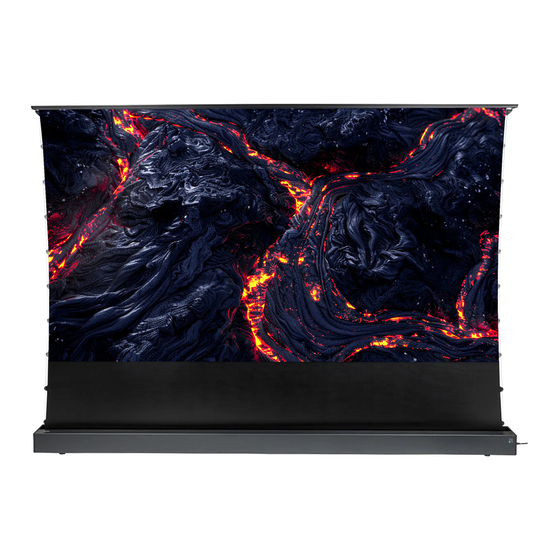
celexon HomeCinema CLR UST
High Contrast Floor scissor screen
- V2.0
Thank you for purchasing this product. For optimum performance and safety, please
read these instructions carefully before connecting or operating this product. Please
retain these instructions for future reference.
Version: 32424_021
Advertisement

Related Manuals for Celexon HomeCinema V2.0


Summary of Contents for Celexon HomeCinema V2.0
- Page 1 Operating instructions celexon HomeCinema CLR UST High Contrast Floor scissor screen - V2.0 Thank you for purchasing this product. For optimum performance and safety, please read these instructions carefully before connecting or operating this product. Please retain these instructions for future reference.
- Page 2 Contact the dealer immediately from whom you purchased the product or celexon directly (Web: www.celexon.co.uk, Mail: info@celexon.co.uk) for further information.
- Page 3 Incorrect installation or use may also invalidate the warranty. • If you are unsure about the use of the product, please contact your specia- list personnel, your dealer or celexon directly (Web: www.celexon.co.uk, Mail: info@celexon.co.uk). • Technical changes and errors excepted.
- Page 4 IMPORTANT NOTES ON CLOTH CLEANING AND CARE Do not use a cloth for cleaning! This cloth material is particularly sensitive to contact with hands or greasy, damp objects. This is due to the texture or cloth surface structure that charac- terises the way this high-contrast ultra-short distance screen works.
-
Page 5: Product Overview
PRODUCT OVERVIEW Cover Joint holder Tension point Upper Cable tensio- articulated arm ning system Joint Projection screen surface Lower articulated arm Housing Levelling screw Side cap 8P8C Communication connection External infrared receiver Operating button Power connection Side view... - Page 6 SCOPE OF DELIVERY 1x Power cable 1x Radio remote control 1x Infrared remote control 1x Infrared Eye (RF) (IR) 1x Radio USB trigger 2x Adjustable mounting 1x Allen key 1x Cleaning brush for pro- bracket jection screen surface 10x 5x40 mm screw + 1x Socket screwdriver 1x Adjustment tool (4 mm) 1x Operating instructions...
-
Page 7: Installation Notes
INSTALLATION NOTES Install the screen in a position that is clearly visible to all viewers! The opti- mum installation height corresponds to the position of the viewers eyes when the screen is extended: eye level = lower third of the screen. Install the screen straight and levelled, otherwise there is a risk that the screen fabric will be rol- led up and unrolled at an angle. - Page 8 MOUNTING ON THE WALL OR ON A FURNITURE BACK PANEL Mark an „installation line“ at the height at which the screen is to be positioned later. The „installation line“ corresponds to the lower edge of the screen housing or the upper edge of the brackets. Mark the centre of the screen on the installation line (Fig.
- Page 9 Attach mounting brackets each with the enclosed 4 screws (5x40 mm) and 4 dowels to your solid concrete or solid brick wall. Adjustable +-1.5° (Fig. 1) For other load-bearing Installation Installation on on wall furniture back structures suitable moun- panel ting accessories! If you are unsure about the correct and safe attach- ment to your supporting structure...
- Page 10 Now that the screen is in its final position in- stalled on the brackets, connect the power supply to the screen and extend the fabric completely. Now check the angle between the screen and your wall and use the Allen key to tighten the adjusting the adjusting screws on the two L-brackets until the fabric is opti- mally straight and parallel to the projection.
-
Page 11: Operation
OPERATION This screen has 6 control options: Housing button, manual switching cycle Wireless USB trigger Wireless remote control Infrared remote control Potential-free control RS485/ RS232 control CONTROL VIA THE CONTROL BUTTON WITH MANUAL SWITCHING CYCLE The button for the manual cycle is located on the end cover of the power sup- ply side of the housing. - Page 12 CONTROL VIA THE RADIO TRIGGER The code pairing of the radio trigger has already been successfully carried out at the factory. The radio trigger controls the screen depending on the power status of the de- vices connected to it. You can connect the trigger to a USB output of your pro- jector, provided that these outputs are switched off when the device is swit- ched off.
- Page 13 The remote control can also be used to reliably control the screen if it is instal- led in furniture, for example, and a clear view of the infrared eye is not possible or not desired. Please note: The radio remote control can also control devices through walls (i.e.
- Page 14 CODE PAIRING/DELETING OF THE RADIO REMOTE CONTROL The radio remote control code has already been successfully paired at the factory. (Note: The infrared remote control generally does not need to be paired). If pairing has been lost, to re-pair, disconnect the screen from the power sup- ply for 10 seconds and then reconnect it to the mains again.
- Page 15 USE OF THE RS485/ RS232 CONTROLLER The RS interface is connected with an RJ45 (8P8C) plug, whereby lines 1 and 2 are the control lines. For the RS485 control unit Line 1 = D- and line 2 = D+. For the RS232 control unit, please refer to the description below: RS485/ RS232 port settings: •...
- Page 16 SETTING THE STOP POINT / HEIGHT OF THE BLACK ADVANCE Note: The black leader can be easily adjusted after the projector and screen have been positioned so that the projection image is aligned with the screen. Changing the adjustment of the black leader is only for fine correction and NOT to compensate for general height differences.
- Page 17 The standard advance is set at approx. 350 mm and must NOT be outside 300 - 400 mm in order not to negatively influence the flatness. Contact celexon if you have any questions about this setting, before chan- • ging the factory default setting.
- Page 18 PROBLEM SOLVING AND USEFUL TIPS • The surface of the black grid fabric is provided with optical „grid teeth“, which enable a targeted reflection of the light beam from the ultra-short throw projector and form the image for the viewer. As shown in the sche- matic diagram: The screen particularly absorbs ambient light from above, the resistance to ambient light from the horizontal sides is weaker, please pay attention to the direction of the light beam when using the screen.
- Page 19 Make absolutely sure that the product, especially the extended cloth, is not exposed to different temperatures at certain points. This uneven tem- perature effect would „stretch“ the material, as colder areas deform diffe- rently to warmer areas, making it very likely that ripples will form and your ultra-short throw projection will show distortions in the image.
- Page 20 HomeCinema CLR UST High Contrast Floor scissor screen - V2.0 Hereby celexon Europe GmbH declares that the celexon HomeCinema CLR UST High Contrast Floor scissor screen - V2.0 complies with the directive 2014/53/ EU. The EU declaration of conformity can be downloaded from the following address: www.celexon.de/zertifikate...
- Page 21 HomeCinema CLR UST High Contrast Floor scissor screen - V2.0 Hereby celexon Europe GmbH declares that the radio equipment type celexon HomeCinema CLR UST High Contrast Floor scissor screen - V2.0 complies with the Radio Equipment Regulations 2017. The UK declaration of conformity can be downloaded from the following address: www.celexon.de/zertifikate...
Need help?
Do you have a question about the HomeCinema V2.0 and is the answer not in the manual?
Questions and answers