
Related Manuals for HUANUO HNTS4B


Summary of Contents for HUANUO HNTS4B
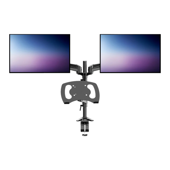
- Page 1 INSTRUCTION MANUAL Rev00(A) HNTS4B Laptop & Monitor Mount (US/CA) 1-800-556-0533 support@huanuoav.com (UK) 44-808-196-3874 www.huanuo.com WWW.
-
Page 2: Important Safety Information
IMPORTANT SAFETY INFORMATION • Please carefully read all instructions before attempting installation. If you do not understand the instructions or have any questions or concerns, please contact our Technical Support at 1-800-556-0533 (US/CA) / 44-808-196-3874 (UK) or Customer Service at support@huanuoav.com. -
Page 3: Product Features
Product Features 360° 180° 360° 360° 360° 27.56″ +85°/ -90° (700mm) C-Clamp Mounting for table edge 0.39 - 3.15″ (10 - 80mm) Grommet Mounting for grommet bolt 0.39 - 2.16″ (10 - 55mm) - Page 4 TENSION ADJUSTMENT SHOULD ONLY BE PERFORMED AFTER MONITOR INSTALLATION Attention DO NOT adjust tension without monitor attached. 1. Verify the weight of your monitor (including accessories) is less than 18 lbs (8 kg). 2. Monitor weight can be found in manual or on manufacturer's website. 3.
- Page 5 Tools Needed (Not lncluded) 7/16-7/8 ″ (11-22mm) Tape Measure Drill (Optional) Drill Bit(Optional) Supplied Parts and Hardware WARNING: This product contains small parts that may pose a choking hazard. Before starting assembly, verify all parts are included and undamaged. Do not use damaged or defective parts.
-
Page 6: Step 1 Install The Base
Supplied Parts and Hardware for Step 3 Bolt Bolt Washer Spacer M4 x 12mm M4 x 30mm 10 x 4.3 x 1mm 10 x 5.2 x 13mm Monitor Plate A x 9 B x 9 C x 8 D x 8 U x 2 Hardware for Step 4 Hardware for Step 5... - Page 7 Option B: For Grommet Mounting B-1 Detach the base [S] entirely. Keep the C-Clamp brace [a], locking plate [b] and grommet bolt [c] for the use of PAGE 08. 5/32" (4mm) 3/16″ (5mm) B-2 Attach the base plate [M] to the bottom of the base. 5/32″...
- Page 8 B-3 Thread the pole [T] into the base. 1/8″ (3mm) B-4 Secure the pole assembly to the desktop by screwing grommet bolt [c] through the desk and locking plate [b] and into the base. φ10-φ50mm NOTE: If a hole is needed for grommet installation, be sure to leave at least 2″...
- Page 9 Step 2 Secure the Arm Assembly to the Pole Assembly 2-1 Slightly loosen the set screws of locating ring [T] and arm support [X]. Slide them and extension arm [Y] in sequence onto the pole at your desired height as shown. Tighten the set screws to secure them.
- Page 10 2-3 Attach the cable management covers [P] to the compression arms [W]. 5/32" (4mm) 2-4 Slide the two compression arms [W] onto the two extension arms [Y], then tighten the set screws. 1/8″ (3mm) Assembled cable management cover face down.
- Page 11 2-5 Connect the VESA plate [V] with the laptop mount [f]. 5/32″ (4mm) Step 3 Attach the Monitor Plates to the Monitors 3-1 Select Monitor Bolts M4 x 30mm M4 x 12mm Hand thread bolts into the threaded inserts on the back of your monitor to determine which bolt (M4 x 12mm or M4 x 30mm ) to use.
- Page 12 Option B:For Curved Monitor The hanging tab is directed toward the 5/32″ (4mm) top of monitor. Step 4 Attach the Monitors and Laptop Mount 5/32″ (4mm) HEAVY! You may need assistance with this step.
- Page 13 1/8″ (3mm) Step 5 Rotation Restriction To ensure proper stability, do not position monitors behind base. Monitors and arms should remain over the desktop. Failure to do so may cause instability, resulting in property damage or injury. Incorrect orientation Correct orientation...
- Page 14 Step 6 Secure the Arm Assembly to the Pole Assembly 6-1 Carefully press down on the compression arm so that it is level with the desk (This may require more force than you think. Ask for help if needed). you can access the adjustment screw increase or decrease the tension to balance the arm.
-
Page 15: Step 8 Rotation Adjustment
Step 7 Tilt and Swivel Adjustment Swivel Adjustment Tilt Adjustment 3/16″ (5mm) Loosen Loosen Tighten Tighten Tighten Tighten Loosen Loosen 3/16″ (5mm) WARNING: Do not overtighten or overloosen the bolts. Directly adjust your monitor by gripping the laptop mount edges / monitor edges (do not press on the screen itself). - Page 16 Step 9 Route Cables Along the Arm Route the cables using the cable management covers [P] on the compression arms and the preassembled covers on the extension arms [Y]. Attach the cable clips [L] to the pole. 1/8″ (3mm) 3/16″ (5mm) 5/32″...
Need help?
Do you have a question about the HNTS4B and is the answer not in the manual?
Questions and answers