Advertisement
#173
'1''1
Means Success In
Electronic
Servicing
tech ...
&lps
Using The FS74A Video Output Jack
Your
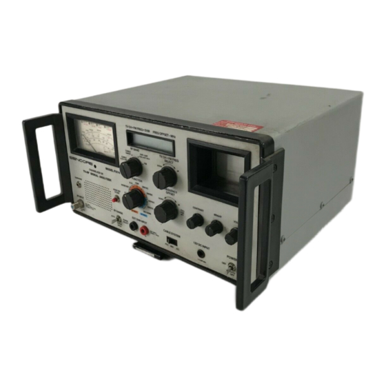
FS74A CHANNELIZER™ SR. thoroughly
analyzes RF distribution signals with several
patented and automatic
tests.
For further analyz-
ing capabilities,
the
FS74A's VIDEO OUT
jack
lets
you view the baseband video signal with an
oscilloscope
or waveform monitor. This Tech Tip
shows
you how
to use
this feature and describes
some
of its
uses and
applications.
How To
Use
The "VIDEO OUT"
Jack
The
"VIDEO
OUT"
jack
is located on
the
FS7
4A's
front
panel
just above
the RF INPUT
jack.
The
output
of
this
jack is a
1 VPP
into 75 ohms
composite video
waveform with
negative-going
sync.
The
1 VPP video signal is present at the
VIDEO
OUT
jack
anytime
you have a
video-modulated
RF
signal
tuned
in
with
your
FS74A CHANNEL-
IZER
SR
.
The
RF
signal
is demodulated
by the
FS74A's detector circuits and amplified into a 1
VPP baseband video
output
signal.
The video
signal is
autoranged with
the
meter and attenu-
ators
so you don't have to continually adjust the
scope's or waveform monitor's
vertical
attenu-
ators
as
the
RF signal changes
amplitude.
NOTE: The level atthe VIDEO OUT
jack will vary
slightly
as
the RF input level
changes.
However,
the
output
will always
be near
1 VPP
so you don't
have to
reset
vertical
attenuators.
To use the VIDEO OUT jack:
1.
Connect an oscilloscope
or waveform
monitor
to the VIDEO
OUT
jack
on the
FS74A. Use a
phono-to-BNC
cable; or
connect the probe to
the
center
conductor, and
ground to the
outer
shield.
2. Connect
an RF
video signal
source to ·the RF
INPUT
jack of
the
FS74A.
Baseband
Video
Fig.
1:
The FS74A
lets
you analyze
the
video
signal
even further by providing a 1 VPP output
signal for
viewing
on an oscilloscope or
waveform monitor.
3.
Turn the FS74A's FUNCTION switch to RF
VIDEO-FM and tune in an RF video signal
with
the FS74A's
microprocessor-controlled
tuner.
4.
Adjust
the oscilloscope
or waveform
monitor
for best
viewing
of the
1 VPP
composite
video
waveform.
NOTE:
Most
oscilloscopes are set up tor
use
with
a x10
probe.
If
a direct cable is used, the am-
plitude shown may appear to be ten times larger
than
the
actual
value.
The VIDEO OUT jack provides a composite
video signal on all of the RF INPUT positions of
the
FUNCTION
switch.
If
one of the F:XT
INPUT
positions of
the
FUNCTION switch
is
chosen,
the
output of
the VIDEO OUT jack is
bypassed.
Uses
And Applications
The
baseband
video signal
of
the FS74A's
VIDEO
OUT
jack
is meant for relative quality and
level
tests of the demodulated
RF
signal.
It
is
not
meant to replace a broadcast quality
demodula-
tor
specially
made
for signal
param
eter tests.
The
following
section explains some
of
the uses
for the
VIDEO OUT
jack of the
FS74A.
Simple Visual Inspection
One of the
most common
uses for
the
FS74A's
VIDEO OUT jack is
to
make simple visual
in-
spections of
the
video waveform
using
your os-
cilloscope or
waveform
monitor. With one
hookup,
you
can
view
the
video waveform
during
regular
I
#173
lilt'
Advertisement
Table of Contents


Need help?
Do you have a question about the FS74A CHANNELIZER SR and is the answer not in the manual?
Questions and answers