Advertisement
Quick Links
1#183
IJ:)I
Means Success In Electronic Servicing
tech •.
.. 1ps
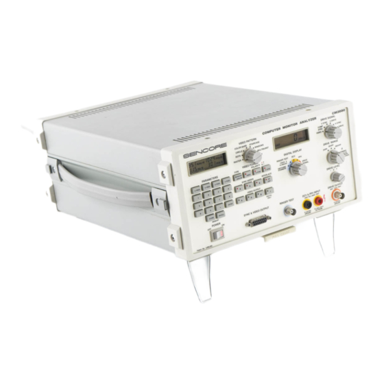
Learning To Use The CM2000
Computer Monitor Analyzer
The CM2000 Computer Monitor
Analyzer
provides the ability to analyze computer
mon itors and isolate defective stages when
troubleshooti
ng.
This Tech Tip will
quickly
familiarize you with the features and
operation of the CM2000 to get you started
making the best use of your Computer
Monitor
Analyzer.
Connecting To A Monitor
The CM2000 SYNC & VIDEO OUTPUT jack
provides all the signals needed to connect to
the input terminal of a computer monitor.
Most computer monitors use one of
several
standard types of input connectors. The
in-
terface connectors adaptthe signals from the
SYNC & VIDEO OUTPUT jack to the standard
SE NC ORE
I
8 B.B.
KHz-H
l
88.B.Hz·V
1888
PIX-H
I
1888
PIX·V
PARAMETERS
EJ
(
RECALL)
IEMORY
POWER
OFF
ON
~[]]]~
Pat.,t
Ho.
3,i90,002
connector
on the mon itor you are servicing.
See Figure 1 to select the interface connector
that matches the
monitor
you are servicing
.
To connect the CM2000 to a monitor:
1.
Turn off the power switch on both the
CM2000 and the
monitor.
2.
Plug the matching interface connector
into the SYNC & VIDEO OUTPUT
jack.
3.
Plug the monitor signal input cable into
the interface
connector.
If the monitor
does not have a
cable,
or if the cable is
too
short,
use the (optional) OUTPUT
EXTENSION CABLE between the SYNC
& VIDEO OUTPUT jack and the interface
connector.
4.
Turn on the CM2000 (wait to turn on the
monitor until you have chosen the
signal format)
.
.-----WARNING------.
Because many computer monitors use a
full-wave "hot chassis
,"
always plug the
monitor you are servicing into an isola-
tion transformer to protect
yourself,
the
monitor,
and your test equipment.
Never isolate your test equipment as
this may defeat that protection
.
Choosing The Signal Format
Each type of computer monitor receives a
particular set of signals from the computer it
is connected
to.
Th is signal format can be
classified
by
the type of computer or video
adaptor circuit which the monitor was de-
signed to work with
.
COMPUTER MONITOR ANALYZER
CM2000
VIDEO PATTERN
CO
LOR BAR
S
ST
AI
R CASE
•
•
CIRC L ( [ )
e
e
WINDO WS
DO TS
e
e
MUL TI
BURST
RA STER
e TE XT
VllEO FORMAT
0
+
TY
PE
POLARITY o
-
DIGITAL
ON.Y
SYNC
.tc
VIDEO OUTPUT
I
GOOD+
'BBB
~
I
BAO
f.
• •
RINGS
DIGITAL DISPLAY
RINGER
TEST
DCV
rl~~~~K~
0
·
PP
V
SWIT CHING
e
e
DRIVE
XFORMERS
SI GNAL
RINGER TEST
DCV
.tc
PPV INPUT
DRIVE SIGNAL
V
SYNC
V
DRI VE
~$~~
~
H
SYNC
VI
DE
O
·~· H DRIVE
DRIVE RANGE
30VPP
3V
P
© P
e
e
e300
VP~
WARNNO:
VOLTAGE
OF
1..P TO JOOVPP
AT TEST
LEJ.OS
DRIVE LEVEL
-
0
+
e
@@~
DRIVE OUTPUT
.JOOV
10mA
l.IAX
®
FLOAT~G
TO 50KV WITH
GROlN)
HV PROBE
r~
PULL
CHART
Advertisement


Need help?
Do you have a question about the CM2000 and is the answer not in the manual?
Questions and answers