Table of Contents
Advertisement
Quick Links
Thank you for purchasing our FRENIC-MEGA series of inverters.
The purpose of this instruction manual is to provide handing information in handling, setting up and operating of the FRENIC-MEGA series of inverters.
Do not use this product until you have full knowledge of the product, safety information and instructions from Instruction Manual (Detailed Version) and Related documents.
[Related Documents]
Instruction Manual (Detailed Version)
INR-SI47-2395□-E
User's Manual
24A7-E-0162□
RS-485 Communication User's Manual
24A7-E-0082□
This manuals can be downloaded in PDF form from QR code in right figure.
Fuji Electric Co., Ltd.
Please feel free to send your comments regarding any errors or omissions you may have found, or any suggestions you may have for generally improving the manual.
In no event will Fuji Electric Co., Ltd. be liable for any direct or indirect damages resulting from the application of the information in this manual.
Thank you for purchasing our FRENIC-MEGA series of inverters.
• This product is designed to drive a three-phase induction motor and three-phase permanent magnet synchronous motor. Read through this instruction manual and be
familiar with the handling procedure for correct use.
• Improper handling might result in incorrect operation, a short life, or even a failure of this product as well as the motor.
• Deliver this manual to the end user of this product.
• Keep this manual in a safe place until this product is discarded.
• For instructions on how to use an optional device, refer to the instruction and installation manuals for that optional device.
• Drawings in this manual may be illustrated without covers or safety shields for explanation of detail parts. Restore the covers and shields in the original state and
observe the description in the manual before starting operation.
Application
• The FRENIC-MEGA is a piece of equipment used to run three-phase motors. It cannot be used for single-phase motors or other applications.
Failure to observe this could result in fire or an accident.
• The FRENIC-MEGA cannot be used as is for applications which may have a direct effect on the human body such as life support machines.
• Strict quality control has been observed in the manufacture of this product, however, safety devices should be installed when the product is used for equipment which
may result in a serious accident or loss in the event of failure.
Failure to observe this could result in an accident.
Installation
• Install on noncombustibles such as metal.
• Do not install near combustibles.
Failure to observe this could result in fire.
• If using an optional DC reactor, there is a possibility of users coming into contact with main circuit terminal block parts (live parts). In such cases, take measures such
as installing the product in a location where it will not easily come into contact with people.
Failure to observe this could result in electric shock or injury.
Wiring
• If no zero-phase current (earth leakage current) detective device such as a ground-fault relay is installed in the upstream power supply line in order to avoid the entire
power supply system's shutdown undesirable to factory operation, install a residual-current-operated protective device (RCD) / earth leakage circuit breaker (ELCB)
individually to inverters to break the individual inverter power supply lines only.
• Connect to the power supply via a molded case circuit breaker or earth leakage circuit breaker (with overcurrent protection function) for each inverter. Use the
recommended molded case circuit breaker or earth leakage circuit breaker, and do not use devices that exceed the recommended capacity.
• Be sure to use the specified wire size.
• Tighten terminals with the prescribed tightening torque.
• If there are multiple inverter and motor combinations, do not use multi-core cables for the purpose of bundling and storing wiring for multiple combinations.
• Do not install a surge suppressor to the inverter output side (secondary side).
• Be sure to connect an optional DC reactor (DCR) when the capacity of the power supply transformer exceeds 500 kVA, and is at least 10 times the inverter rated
capacity.
Failure to observe this could result in fire.
• Ground the inverter in compliance with the national or local electric code.
• Be sure to ground the inverter ground terminal [*G] grounding wire.
Failure to observe this could result in electric shock or fire.
• Wiring work should be carried out by qualified professionals.
• Carry out wiring work after ensuring that the power has been turned OFF.
Failure to observe this could result in electric shock.
• Always carry out wiring after installing the unit.
Failure to observe this could result in electric shock or injury.
• Ensure that the number of phases and rated voltage of the product input power supply matches that for the connected power supply.
• Do not connect the power lines to the inverter output terminals (U, V, W).
• When connecting a DC braking resistor (DBR), never connect it to terminals other than terminals P(+) and DB.
Failure to observe this could result in fire or an accident.
• Control signal lines generally do not have a reinforced insulation coating, and therefore if control signal lines come into contact with live parts of the main circuit, the
insulation coating may be damaged for some reason. In such a case, there is a danger that high voltage from the main circuit will be applied to the control signal lines,
and therefore care should be taken to ensure that they do not come into contact with live parts of the main circuit.
Failure to observe this could result in an accident or electric shock.
• Switch all switches after first waiting for at least 5 minutes for FRN0115G2S-2G / FRN0060G2□-4G or lower inverters, or 10 minutes for FRN0146G2S-2G /
FRN0075G2□-4G or higher inverters, ensuring that the LED monitor and charge lamp are off, and using a device such as a tester to ensure that the DC intermediate
circuit voltage across main circuit terminals P and N has dropped to a safe level (+25 VDC or less).
Failure to observe this could result in electric shock.
Operation
• Be sure to attach the inverter surface cover before turning the power ON. Do not remove the surface cover while the power is ON.
• Do not operate the unit with wet hands.
Failure to observe this could result in electric shock.
• If the product stops after being tripped when the retry function is selected, depending on the cause of the trip, the product will restart automatically, and the motor will
rotate. Design the machinery so that human body and peripheral equipment safety is ensured even when the auto-resetting succeeds. Design machines in such a
way as to ensure the safety of the human body and surrounding area even when operation is resumed.
• There may be times when the stall prevention function (torque limiting) causes the product to run at an acceleration / deceleration time or speed different from the set
values. Design machines in such a way that safety is ensured even at such times.
Failure to observe this could result in an accident.
• The keypad
key is enabled only when keypad operation is selected with function code F02. Please prepare a separate EMERGENCY STOP button. When
function code H96 has been set to "0" or "2", the
key will be disabled if the operation command method is changed from operation command with the keypad by
selecting link operation "LE".
• If any of the protective functions has been activated, first remove the cause. Then, after checking that all run commands are set to OFF, release the alarm. If the alarm
is released while any run command is set to ON, the inverter may supply the power to the motor, running the motor.
Failure to observe this could result in an accident.
• By selecting the momentary power failure resume operation (F14 = 3 to 5), operation will resume automatically following recovery. Design machines in such a way as
to ensure operator safety even when operation is resumed.
• Set function codes after ensuring a sufficient understanding of this Instruction Manual. If operation is performed after recklessly changing function code data, the
motor may rotate at a torque and speed at which the machine is unable to tolerate.
• When auto tuning is started, the motor rotates. Conduct a sufficient check to ensure that there is no danger even when the motor rotates.
Failure to observe this could result in an accident or injury.
• Even if the inverter cuts off the supply of power to the motor, if voltage is being applied to main power supply input terminals L1/R, L2/S, and L3/T, voltage may be
output to inverter output terminals U, V and W.
• Even if the motor is stopped by DC braking operation or pre-excitation operation, voltage will be output to the inverter output U, V and W terminals.
Failure to observe this could result in electric shock.
• Inverter high-speed operation settings can be specified easily. If settings are changed, use the product after sufficiently checking the motor and machine specification.
Failure to observe this could result in injury.
Maintenance and inspection, part replacement
• Carry out inspection after waiting at least 5 minutes for FRN0115G2S-2G / FRN0060G2□-4G or lower inverters, or 10 minutes for FRN0146G2S-2G / FRN0075G2
□-4G or higher inverters after turning OFF the power. Furthermore, ensure that the LED monitor and charge lamp are OFF, and use a device such as a tester to
ensure that the DC intermediate circuit voltage across main circuit terminals P (+) and N (-) has dropped to a safe level (+25 VDC or less).
Failure to observe this could result in electric shock.
• Be sure to perform the daily inspection and periodic inspection described in the instruction manual. Lengthy use of the product without inspection could result in
inverter failure and damage, or accident and fire.
• A periodic inspection cycle of 1 to 2 years is recommended, however, the cycle may be shortened depending on the usage conditions.
• It is recommended that parts for periodic replacement be replaced after the standard number of years indicated in the instruction manual. Lengthy use of the product
without replacing parts could result in inverter failure and damage, or accident and fire.
• Contact outputs [30A/B/C] and [Y5A/C] use relays, and may remain ON or OFF, or in an indefinite state when the life is reached. In the interests of safety, equip the
product with an external protection function.
Failure to observe this could result in fire or an accident.
• Maintenance and inspection, and part replacement should only be carried out by the authorized personnel.
• Remove all metal objects (watches, rings, etc.) before beginning work.
• Be sure to use insulated tools.
• Never modify the product.
Failure to observe this could result in electric shock or injury.
Installation
• Do not hold the surface cover when transporting the product.
Failure to observe this could result in injury if the product is dropped.
• Take measures to prevent foreign material such as lint, wastepaper, wood shavings, dust, or metal scraps getting into the inverter, or adhering to the cooling fan.
• Use the specified screws for changing the mounting base.
Failure to observe this could result in fire or an accident.
• Do not install or run inverters with damaged external or internal parts.
Failure to observe this could result in fire, an accident, or injury.
Wiring
• The inverter, motor and wiring generate electric noise, which may cause nearby sensors and devices to malfunction. Employ noise countermeasures to prevent
malfunction.
Failure to observe this could result in an accident.
Operation
• The cooling fans and braking resistors become very hot. Do not touch.
Failure to observe this could result in burns.
• Mechanical holding is not possible with the inverter brake function.
Failure to observe this could result in injury.
• The digital input terminals are equipped with a function used to start and stop operation or change the speed command with the "FWD" operation command or "BX"
free-run command and so on. Depending on the digital input terminal status, operation may start suddenly, or the speed may change significantly simply by changing
the function code settings. Make changes to function code settings after sufficiently ensuring safety.
• With digital input, functions ("SS1, SS2, SS4, SS8", "Hz2/Hz1", "Hz/PID", "IVS", "LE", etc.) used to change the operation procedure for operation commands or
command procedure for speed commands can be assigned. Depending on the conditions, changes to these signals may result in operation being started suddenly or
the speed changing suddenly.
• Ensure safety before modifying customizable logic related function code settings (U codes and related function codes) or turning ON the "Cancel customizable logic"
terminal command CLC. Depending upon the settings, such modification or cancellation of the customizable logic may change the operation sequence to cause a
sudden motor start or an unexpected motor operation. Carry out a sufficient safety check beforehand.
Failure to observe this could result in an accident or injury.
Disposal
• If disposing of the FRENIC-MEGA, handle as industrial waste.
Failure to observe this could result in injury.
INR-SI47-2392a-E
2nd Edition, May 2021
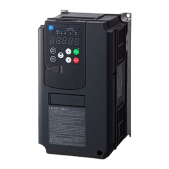
Instruction Manual
FRENIC-MEGA series
FRN□□□□G2□-□G
Instruction manual QR code
https://www.fujielectric.com/products/inverter/frenic-megag2/download/_pr/
Chapter 1 BEFORE USE
1.1
Acceptance Inspection (Nameplate and Inverter Type)
Unpack the package and check the following:
(1)
Ensure that the package contains both the inverter unit and instruction manual (this manual), and that the product has suffered no damage (breakage, dents, parts
that have fallen off) during transport.
(2)
The (a) Main Nameplate and (b) Sub Nameplate shown in Figure 1-1 are affixed to the inverter. Ensure that the product is the same as the one ordered.
Figure 1-1 (a) Main Nameplate
TYPE: Type of inverter
FRN 0003 G
Code
Series name
FRN
FRENIC series
3-phase 200 V series
Applicable motor rating
Code
HHD kW (HP) HND kW (HP)
0003
0.4 (1/2)
-
0005
0.75 (1)
-
-
0018
3.7 (5)
-
0032
5.5 (7.5)
7.5 (10)
0059
11 (15)
15 (20)
0346
75 (100)
90 (125)
0432
90 (125)
110 (150)
3-phase 400 V series
Applicable motor rating
Code
HHD kW (HP) HND kW (HP)
0002
0.4 (1/2)
-
0003
0.75 (1)
-
-
0009
3.7 (5)
-
0018
5.5 (7.5)
7.5 (10)
0031
11 (15)
15 (20)
1170
500 (800)
630 (900)
1386
630 (900)
710 (1000)
SER.No.:
Product number
Production year and week
T31 A 1 2 3 A 0 5 7 9 E AA
3 0 1
Production week: This indicates the week number that is numbered from 1st week of January.
Production year:
Product version
If you suspect the product is not working properly or if you have any questions about your product, contact your Fuji Electric representative.
Chapter 2 INSTALLATION AND WIRING
2.1
Operating Environment
Install the inverter in an environment that satisfies the requirements listed inTable 2-1.
Table 2-1 Operating environment
Item
Site location
Indoors Environmental conditions: IEC60721-3-3:3C2
Ambient temperature
-10 to +55 °C (14 to 131ºF) (Current derating is necessary in the +50 to +55 ºC (122 to 131ºF) range.)
When installed closely side-by-side (FRN0115G2S-2G / FRN0060G2□-4G or lower): -10 to +40 °C (14 to 104ºF)
Relative humidity
5 to 95% RH (there should be no condensation)
Atmosphere
The inverter must not be exposed to dust, direct sunlight, corrosive gases, flammable gases, oil mist, vapor or water droplets.
(Pollution degree 2 (IEC60664-1)) (Note 1)
The atmosphere can contain a small amount of salt (0.01 mg/cm
The inverter must not be subjected to sudden changes in temperature that will cause condensation to form.
Altitude
1,000 m (3,300 ft) max. (Note 2)
Atmospheric pressure
86 to 106 kPa
Vibration
Type of inverter
FRN0115G2S-2G or lower,
FRN0060G2□-4G or lower
FRN0288G2S-2G or lower,
FRN0180G2□-4G or lower
FRN0346G2S-2G or higher,
FRN0216G2□-4G or higher
(Note 1) Do not install the inverter in an environment where it may be exposed to lint, cotton waste or moist dust or dirt which will clog the heat sink of the inverter. If the
inverter is to be used in such an environment, install it in cabinet to prevent lint, etc. getting in.
(Note 2) If you use the inverter in an altitude above 1,000 m (3,300 ft), you should apply an output current derating factor as listed in Table 2-2
Table 2-2 Output Current Derating Factor in Relation to Altitude
Altitude
1,000 m (3,300 ft) or less
1,000 to 1500 m (3,300 to 4,900 ft)
1,500 to 2,000 m (3,300 to 4,900 ft)
2,000 to 2,500 m (3,300 to 4,900 ft)
2,500 to 3,000 m (3,300 to 4,900 ft)
Fuji Electric strongly recommends installing inverters in a panel for safety reasons, in particular, when installing the ones whose enclosure rating is IP00.
When installing the inverter in a place out of the specified environmental requirements, it is necessary to derate the inverter or consider the panel engineering design
suitable for the special environment or the panel installation location.
2.2
Installation
2.2.1
Installation Surface
Please install the inverter on noncombustibles such as metal. Also, do not mount it upside down or horizontally.
2.2.2
Surrounding Space
Secure the surrounding space shown in Figure 2-1 and Table 2-3. If enclosing the product in a cabinet and so on, be sure to provide adequate ventilation to the cabinet, as
the ambient temperature may rise. Do not contain it in small enclosures with low heat dissipation capacity.
■ Installation of Multiple Inverters
If installing two or more units inside the same equipment or cabinet, they must be installed side
by side as a rule. If vertical installation is unavoidable, install partitions to prevent heat
dissipation from inverters below affecting those above.
With FRN0115G2S-2G / FRN0060G2□-4G or lower inverters, only in the case of an ambient
temperature of 40°C (104°F) or below is it possible to install inverters and converters closely
together horizontally.
Table 2-3 Surrounding space mm (inch)
Type of Inverter
FRN□□□□
FRN□□□□
A
G2S-2G
G2□-4G
0003 to 0008
0002 to 0004
50 (1.97)
0011 to 0115
0006 to 0060
10 (0.39)
100 (3.9)
0146 to 0432
0075 to 0520
50 (1.97)
—
0650 to 1386
150 (5.9)
C:
Space in front of the inverter unit
■ Installation with External Cooling
The external cooling installation reduces the generated heat inside the panel by dissipating approximately 70% of the total heat generated (total heat loss) by mounting the
cooling fins protruding outside the equipment or cabinet.
Installation with external cooling is possible for inverters FRN0115G2S-2G / FRN0060G2□-4G or lower with the addition of an external cooling attachment (option), and for
FRN0146G2S-2G / FRN0075G2□-4G or higher inverters by moving the mounting base. (For external cooling attachment (option) external drawings, refer to Chapter 11
section 11.16 in the User's Manual, and for details on the installation method for FRN0146G2S-2G / FRN0075G2□-4G inverters or higher, refer to Chapter 2 section 2.1 in
the same manual.)
Take measures to prevent foreign material such as lint, wastepaper, wood shavings, dust, or metal scraps getting into the inverter, or adhering to the cooling fan.
2.2.3
Removal and Attachment of the Front Cover and the Terminal Cover
Carry out wiring work in the following order (The descriptions assume that the inverter has already been installed). If using the RS-485 communication cable for such
purposes as remotely operating the keypad, always remove the RS-485 communication cable from the RJ-45 connector before removing the front cover.
(1) FRN0115G2S-2G / FRN0060G2□-4G or lower inverters
1)
Loosen the screws of the front cover. Hold both sides of the front cover with the hands, slide the cover downward, and pull. Then remove it to the upward direction.
2)
Push the wiring guide upward and pull. Let the wiring guide slide and remove it.
3)
After routing the wires, attach the wiring guide and the front cover reversing the steps above.
Front cover attachment screw
Figure 2-3 Removal of front cover and wiring guide (for FRN0031G2S-4G)
(b) Sub Nameplate
2
S
2
G
-
Code
Destination/Manual
G
Global/English
Code
Input power source
2
3-phase 200V
4
3-phase 400V
Code
Enclosure
S
Standard (basic type)(IP20/IP00)
E
EMC filter built-in type
Code
Order of development
2
2
Code
Applicable range
High performance,
G
multifunctional type
The 1st week of January is indicated as '01'.
Last digit of year
Specifications
2
or less per year).
2 to less than 9 Hz
9 to less than 20 Hz
20 to less than 55 Hz
2
5.9 m/s
2
9.8 m/s
3 mm
(max. amplitude)
2
2 m/s
2
2 m/s
Output current derating factor
1.00
0.97
0.95
0.91
0.88
B
A
A
B
C
0 (0)
* Current derating is necessary in the +50
B
to +55◦C (122 to 131◦F) range.
100 (3.9)
150 (5.9)
Figure 2-1 Installation
Figure 2-2 External cooling installation
direction
Front cover
Wiring guide
55 to less than 200 Hz
2
1 m/s
method
Advertisement
Table of Contents

Related Manuals for Fuji Electric FRENIC-MEGA FRN G2 G Series


Summary of Contents for Fuji Electric FRENIC-MEGA FRN G2 G Series
- Page 1 Applicable motor rating 3-phase 200V Code In no event will Fuji Electric Co., Ltd. be liable for any direct or indirect damages resulting from the application of the information in this manual. HHD kW (HP) HND kW (HP) 3-phase 400V 0003 0.4 (1/2)
- Page 2 Table 2-7 Recommended rod terminals (2) FRN0146G2S-2G / FRN0075G2□-4G or higher inverters Loosen the screws of the front cover. Hold both sides of the front cover by hand, and slide the cover upward to remove. Type Wire size After carrying out wiring work, align the top of the front cover with the hole on the cover, and reattach using the opposite procedure to that in Figure 2-4. With insulating collar Without insulating collar Open the keypad case to expose the control PCB.
- Page 3 : Functions assigned with function code E70 can be used. Hold down (for 1 second) to turn 1) In the event that breakdown occurs during the product’s warranty period which is the responsibility of Fuji Electric, Fuji Electric will replace or repair the part of the the function ON and OFF.
- Page 4 (26.7) PC30UD69V350□ (13.5) • Not all Fuji Electric products in Europe are necessarily imported by the above importer. If any Fuji Electric products are exported to Europe via another importer, FRN0112G2□-4G /170M3469 please ensure that the importer is clearly stated by the customer.
Need help?
Do you have a question about the FRENIC-MEGA FRN G2 G Series and is the answer not in the manual?
Questions and answers