Table of Contents
Advertisement
Quick Links
Advertisement
Table of Contents
Troubleshooting

Related Manuals for National Instruments PXI-8310


Summary of Contents for National Instruments PXI-8310
- Page 1 PXI-8310...
- Page 2 NI CardBus-8310-to-PXI Expansion User Manual NI CardBus-8310-to-PXI Expansion User Manual August 2005 371665A-01...
- Page 3 For further support information, refer to the appendix. To comment Technical Support and Professional Services on National Instruments documentation, refer to the National Instruments Web site at ni.com/info and enter the info code feedback. © 2005 National Instruments Corporation. All rights reserved.
- Page 4 The reader should consult National Instruments if errors are suspected. In no event shall National Instruments be liable for any damages arising out of or related to this document or the information contained in it.
- Page 5 These classes are known as Class A (for use in industrial-commercial locations only) or Class B (for use in residential or commercial locations). All National Instruments (NI) products are FCC Class A products. Depending on where it is operated, this Class A product could be subject to restrictions in the FCC rules. (In Canada, the Department of Communications (DOC), of Industry Canada, regulates wireless interference in much the same way.) Digital...
- Page 6 Conventions This manual provides information on the installation and use of an NI CardBus-8310-to-PXI Expansion system. The following conventions are used in this manual: » The » symbol leads you through nested menu items and dialog box options to a final action. The sequence File»Page Setup»Options directs you to pull down the File menu, select the Page Setup item, and select Options from the last dialog box.
-
Page 7: Table Of Contents
RJ-45 Connector ................1-3 NI CardBus-8310-to-PXI Cable Options..........1-3 Before Installation......................1-3 Parts List......................1-4 Protecting Against Electrostatic Discharge .............1-4 NI PXI-8310 Overview....................1-5 Chapter 2 Hardware and Software Installation Installation Instructions....................2-1 Install the Software Driver ................2-1 Windows 2000/XP (Without XP Service Pack 2) ......2-2 Windows XP (With Service Pack 2)..........2-2... - Page 8 Contents Appendix B Specifications Power Requirements...................... B-1 Physical.......................... B-1 Dimensions...................... B-2 Operating Environment................... B-2 Storage Environment..................B-2 Appendix C Troubleshooting NI PXI-CardBus-8310 Cards Contacting Technical Support ..................C-1 Troubleshooting......................C-2 Error Code (Yellow Exclamation Mark) in Device Manager ........C-8 Appendix D Technical Support and Professional Services Index...
-
Page 9: Functional Overview
The CardBus-to-PXI link consists of an NI CardBus-8310 card in the laptop computer connected via cabling to an NI PXI-8310 module in slot 1 of a PXI chassis. For convenience, you can purchase either a complete... -
Page 10: Functional Unit Descriptions
Figure 1-1 shows the basic architecture of an NI CardBus-8310-to-PXI system. The NI CardBus-8310 consists of a CardBus connector, a CardBus-to-PXI bridge, a StarFabric bridge and two RJ-45 connectors. The NI PXI-8310 consists of two RJ-45 connectors, a StarFabric bridge, and a PXI connector. RJ-45... -
Page 11: Rj-45 Connector
The NI CardBus-8310-to-PXI is available with cables of various lengths. Table 1-1 shows the cables that are available from National Instruments. Table 1-1. National Instruments CardBus-8310-to-PXI Cables Cable Length (meters) -
Page 12: Parts List
NI CardBus-8310 3 meter CAT5-e cables with 4 ferrites (two ferrites for each cable). 10-meter and 14-meter cables may be purchased separately. NI PXI-8310 Software Installation CD (will contain the software driver, full user manual, and Documents of Conformity) Installation Guide... -
Page 13: Ni Pxi-8310 Overview
LED will be lit on the front panel. Each port requires two CAT5-e cables. You must connect the RX jack of the CardBus-8310 to the TX jack of the PXI-8310, and the TX jack of the CardBus-8310 to the RX jack of the PXI-8310. - Page 14 A faulty cable may link some differential pairs while disabling others and the LEDs can be used to isolate the faulty cable. If replacing the cable does not resolve the issue, there may be a problem with the StarGen bridge. In that case, contact National Instruments with the information described in the...
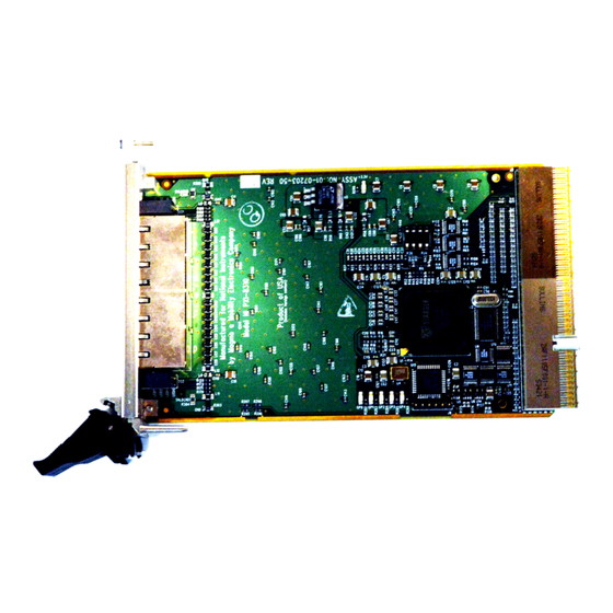
- Page 15 Interface 1 L0 Link Status LEDs (0–3) 3 L1 Link Status LEDs (0–3) 2 Receiver Ports (RX) 4 Transmitter Ports (TX) Figure 1-2. Front Panel of the NI PXI-8310 Expansion Card © National Instruments Corporation NI CardBus-8310-to-PXI Expansion User Manual...
-
Page 16: Hardware And Software Installation
CardBus slot. If you are using Windows XP, the “Found New Hardware” dialog box will only appear if you have Service Pack 2 installed. This dialog appears by default under Windows 2000. © National Instruments Corporation NI CardBus-8310-to-PXI Expansion User Manual... -
Page 17: Windows 2000/Xp (Without Xp Service Pack 2)
Chapter 2 Hardware and Software Installation Windows 2000/XP (Without XP Service Pack 2) If you do not have your system configured to allow autorun CDs, you must run to install the NI CardBus-8310 driver. SETUP.EXE Follow the prompts to install the software. When the software prompts you reboot, do so. - Page 18 Figure. 2-1. Click Next. The dialog box shown in Figure 2-3 will appear. Figure 2-3. Reboot Dialog Box Choose No and click Finish. Manually shut down your computer. © National Instruments Corporation NI CardBus-8310-to-PXI Expansion User Manual...
-
Page 19: Install The Pxi Cards
Carefully position the PXI chassis so that the supplied cables will conveniently reach from the connector of the NI CardBus-8310 card to the connectors on the NI PXI-8310. Install one of the provided ferrites on each end of each of your cables. -
Page 20: Install The Ni Cardbus-8310
Transmit (TX) port on the NI CardBus-8310 card, then attach the other end to the Receive (RX) port on the NI PXI-8310 card. The LEDs on the NI PXI-8310 will light up if the cables are connected properly. - Page 21 PXI chassis, and plug the NI CardBus-8310 card into the laptop. Power up the host computer. Both LEDs should be lit on the NI PXI-8310. Flashing LEDs indicate that the wires are reversed. If the LEDs are flashing, switch the wires and begin again at step 1.
- Page 22 Hardware and Software Installation Figure 2-5. Software Installation Options Choose automatic installation and click Next. Figure 2-6. Installation Wizard Completion Dialog Box Once the StarGen PCI to PCI bridge installation is complete, click Finish. © National Instruments Corporation NI CardBus-8310-to-PXI Expansion User Manual...
-
Page 23: Verifying The Installation
Chapter 2 Hardware and Software Installation The Found New Hardware Wizard dialog box will appear again, and will find another PCI to PCI bridge, because there are two bridge chips. Follow the instructions outlined in steps 4 through 7 to successfully install the second PCI to PCI bridge. -
Page 24: Powering Down
It is recommended that you first shut down the host computer correctly, and then power down the PXI chassis to avoid a computer lock-up. © National Instruments Corporation NI CardBus-8310-to-PXI Expansion User Manual... -
Page 25: Running The System
NI CardBus-8310 driver, and then select Add/Remove. Additional Notes The following notes are observations made during the testing of the NI CardBus-8310 and the NI PXI-8310. System Hierarchy To connect additional PXI chassis through MXI-4, please connect them to the first PXI bus segment in the first chassis as shown in Figure 2-8. The preferred connection style is a Star configuration, rather than a daisy-chain, which is shown in Figure 2-9. -
Page 26: System Boot
NI Measurement & Automation Explorer (MAX) The initial launch of MAX may take a long time (several minutes) to discover all the devices in a system with a large number of modules and chassis. © National Instruments Corporation 2-11 NI CardBus-8310-to-PXI Expansion User Manual... -
Page 27: Pciscope
PCIScope and other utilities offered by APSoft. An evaluation version of PCIScope can be downloaded from . (You can purchase a license from APSoft for use beyond www.tssc.de the evaluation period for $49.95.) © National Instruments Corporation NI CardBus-8310-to-PXI Expansion User Manual... - Page 28 Appendix A PCIScope Figure A-1. Example of PCIScope Interface The data can be stored as a file on your computer. You may be *.bpd requested to email this file to if you are experiencing support@ni.com configuration problems. NI CardBus-8310-to-PXI Expansion User Manual ni.com...
-
Page 29: Power Requirements
5 V ........... 1.5 A Maximum 3.3 V ........0.40 A 5 V ........... 1.7 A Physical Sustained Throughput Input ..........Up to 50 MB/s Output ..........Up to 10 MB/s © National Instruments Corporation NI CardBus-8310-to-PXI Expansion User Manual... -
Page 30: Dimensions
Appendix B Specifications Dimensions NI CardBus-8310........Type II PC Card NI PXI-8310 ...........1-slot 3U PXI module Slot requirements ........One 3U PXI system controller slot Maximum cable length ......14 m Compatibility ..........Fully compatible with the PXI Hardware Specification 2.1 Operating Environment Temperature CardBus-8310........0 to 40 °C... - Page 31 Refer to the Declaration of Conformity (DoC) for this product for any additional Note regulatory compliance information. The DoC for this product has been included as a digital document on your driver CD. © National Instruments Corporation NI CardBus-8310-to-PXI Expansion User Manual...
-
Page 32: Troubleshooting Ni Pxi-Cardbus-8310 Cards
While this appendix contains a number of troubleshooting tips for resolving issues that may be experienced with NI CardBus-8310 cards, extreme cases may require you to contact National Instruments Technical Support. You can find that contact information in the Technical Support and Professional appendix of this manual. -
Page 33: Troubleshooting
No LEDs are lit on the NI PXI-8310 card. The LEDs are flashing on the NI PXI-8310 card. One or more LEDs are not lit on the NI PXI-8310 card. An error is returned after inserting the CardBus card before installing the CardBus card driver. - Page 34 Power down the laptop and the chassis system. Power up the chassis first and then power up the computer. Issue: One or more LEDs are not lit on the NI PXI-8310 card. This may be a defective hardware. Please call customer service for support.
- Page 35 – Power down the laptop and the chassis system. Power up the chassis first and then the computer. • If there are no LEDs lit on the NI PXI-8310 card: – Verify that the CardBus card is inserted properly. –...
- Page 36 Devices by connection, there should be no errors. At this point, power down and begin adding PXI cards one by one, powering up to check that there are no errors in Device Manager after installing each card. This can isolate problematic hardware/software. © National Instruments Corporation NI CardBus-8310-to-PXI Expansion User Manual...
- Page 37 CardBus card or modem, etc. – Verify that you are using the correct expansion interface cards. You should be using an NI CardBus-8310 card in your host computer, and an NI PXI-8310 card in your PXI chassis. – Re-seat both cable connections. –...
- Page 38 Appendix C Troubleshooting NI PXI-CardBus-8310 Cards If the problem occurs consistently, please contact National Instruments for technical support. Issue: The application or program failed to communicate with the PXI device card during an operation. • Make sure the PXI chassis is properly powered.
-
Page 39: Error Code (Yellow Exclamation Mark) In Device Manager
Appendix C Troubleshooting NI PXI-CardBus-8310 Cards • If another card that has worked in the past is available, try it in the same slot. • Plug the card into a different slot in the chassis, to ensure that the chassis is functional. Error Code (Yellow Exclamation Mark) in Device Manager The following section interprets the error codes corresponding to the... - Page 40 If you don’t have another CardBus socket, please contact technical support. For more information on the Windows Device Manager Error Codes please visit the Microsoft page: http://www.microsoft.com/resources/documentation/ Windows/XP/all/reskit/en-us/Default.asp?url=/resources/ documentation/Windows/XP/all/reskit/en-us/ prjk_dec_lgsc.asp © National Instruments Corporation NI CardBus-8310-to-PXI Expansion User Manual...
-
Page 41: Technical Support And Professional Services
Technical Support and Professional Services Visit the following sections of the National Instruments Web site at for technical support and professional services: ni.com • Support—Online technical support resources at ni.com/support include the following: – Self-Help Resources—For answers and solutions, visit the... - Page 42 Appendix D Technical Support and Professional Services • Declaration of Conformity (DoC)—A DoC is our claim of compliance with the Council of the European Communities using the manufacturer’s declaration of conformity. This system affords the user protection for electronic compatibility (EMC) and product safety.
-
Page 43: Index
(NI resources), D-1 latencies functional overview, 1-1 Measurement and Automation Explorer functional unit descriptions, 1-2 (MAX), 2-11 system boot, 2-11 help, technical support, D-1 Measurement and Automation Explorer (MAX), 2-11 © National Instruments Corporation NI CardBus-8310-to-PXI Expansion User Manual... - Page 44 Index specifications electromagnetic compatibility, B-3 National Instruments support and safety, B-2 services, D-1 StarFabric bridge, 1-2 NI CardBus-8310, 1-2 supported operating systems, 2-1 NI PXI-8310, 1-5 system boot latencies, 2-11 front view (figure), 1-7 system hierarchy, 2-10 NI support and services, D-1...
Need help?
Do you have a question about the PXI-8310 and is the answer not in the manual?
Questions and answers