
Related Manuals for National Instruments IMAQ PCI-1410


Summary of Contents for National Instruments IMAQ PCI-1410
- Page 1 IMAQ IMAQ PCI-1410 User Manual High-Quality Monochrome Image Acquisition Device for PCI Chassis IMAQ PCI-1410 User Manual January 2005 373793B-01...
- Page 2 For further support information, refer to the Technical Support and Professional Services appendix. To comment on National Instruments documentation, refer to the National Instruments Web site at ni.com/info and enter the info code feedback. © 2004–2005 National Instruments Corporation. All rights reserved.
- Page 3 The reader should consult National Instruments if errors are suspected. In no event shall National Instruments be liable for any damages arising out of or related to this document or the information contained in it.
- Page 4 These classes are known as Class A (for use in industrial-commercial locations only) or Class B (for use in residential or commercial locations). All National Instruments (NI) products are FCC Class A products. Depending on where it is operated, this Class A product could be subject to restrictions in the FCC rules. (In Canada, the Department of Communications (DOC), of Industry Canada, regulates wireless interference in much the same way.) Digital...
- Page 5 Conventions The following conventions are used in this manual: <> Angle brackets that contain numbers separated by an ellipsis represent a range of values associated with a bit or signal name—for example, DIO<3..0>. » The » symbol leads you through nested menu items and dialog box options to a final action.
-
Page 6: Table Of Contents
Contents Chapter 1 Introduction About the IMAQ 1410 Device..................1-1 Software Overview ......................1-2 NI-IMAQ Driver Software ................1-3 National Instruments Application Software ............1-3 Vision Builder for Automated Inspection.........1-3 Vision Development Module ............1-4 Integration with DAQ..................1-4 Vision and Motion...................1-5 Chapter 2 Installation Necessary Items ......................2-1 Optional Equipment .......................2-2... - Page 7 Video Input Channels ....................4-1 BNC Connector ......................4-1 Digital I/O Connector ....................4-2 Digital I/O Connector Signal Connection Descriptions........4-3 Appendix A Specifications Appendix B Custom Cables Appendix C Technical Support and Professional Services Glossary Index IMAQ PCI-1410 User Manual viii ni.com...
-
Page 8: About The Imaq 1410 Device
The IMAQ 1410 is easy to install and configure. It ships with NI-IMAQ, the National Instruments driver software you can use to directly control the IMAQ 1410 and other National Instruments IMAQ devices. With NI-IMAQ, you can quickly and easily start the applications without having to program the device at the register level. -
Page 9: Software Overview
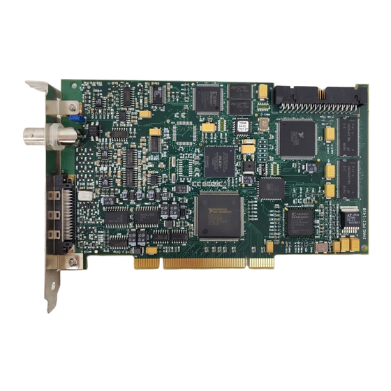
4 RTSI Bus Connector Figure 1-1. IMAQ PCI-1410 Parts Locator Diagram Software Overview Programming the IMAQ 1410 requires the NI-IMAQ driver software for controlling the hardware. National Instruments also offers the following application software packages for analyzing and processing your acquired images. •... -
Page 10: Ni-Imaq Driver Software
NI-IMAQ performs all functions required for acquiring and saving images but does not perform image analysis. For image analysis functionality, refer to the National Instruments Application Software section of this chapter. NI-IMAQ is also the interface path between the IMAQ 1410 and LabVIEW, ™... -
Page 11: Vision Development Module
LabVIEW to add functionality to the generated VI. Integration with DAQ Platforms that support NI-IMAQ also support NI-DAQ and a variety of National Instruments DAQ devices. This allows integration between IMAQ devices and National Instruments DAQ products. IMAQ PCI-1410 User Manual... -
Page 12: Vision And Motion
Chapter 1 Introduction Vision and Motion Use National Instruments high-performance stepper and servo motion control products with pattern matching software in inspection and guidance applications, such as locating alignment markers on semiconductor wafers, guiding robotic arms, inspecting the quality of manufactured parts, and locating cells. -
Page 13: Installation
– Measurement Studio ❑ IMAQ BNC-1 shielded, 75 Ω BNC cable for VIDEO0, included with the IMAQ 1410 ❑ Video camera or other video source ❑ Pentium-based PCI computer running Windows 2000/NT/XP/Me/98 © National Instruments Corporation IMAQ PCI-1410 User Manual... -
Page 14: Optional Equipment
Chapter 2 Installation Optional Equipment National Instruments offers the following products for use with the IMAQ 1410: • IMAQ A6822 BNC breakout box and cable for trigger and additional camera support • RTSI bus cables for connecting the IMAQ 1410 to DAQ, Motion Control, and IMAQ hardware •... - Page 15 Installation not use it until service-trained personnel can check its safety. If necessary, return the device to National Instruments for repair. Keep away from live circuits. Do not remove equipment covers or shields unless you are trained to do so. If signal wires are connected to the device, hazardous voltages can exist even when the equipment is turned off.
- Page 16 Chapter 2 Installation National Instruments measurement products may be classified as either Caution Installation Category I or II. Operate products at or below the Installation Category level specified in the hardware specifications. Installation Category : Measurement circuits are subjected to working...
-
Page 17: Installation
IMAQ 1410 straight down until it rests firmly in the expansion slot. Reinstall the bracket-retaining screw to secure the IMAQ 1410 to the back panel rail. Visually verify the installation. 10. Replace the computer cover, and plug in the computer. © National Instruments Corporation IMAQ PCI-1410 User Manual... -
Page 18: Hardware Overview
Hardware Overview This chapter describes the features of the IMAQ PCI-1410 device and includes information about acquisition modes, analog front-end considerations, and clamping. Functional Overview The IMAQ 1410 features a flexible, high-speed data path optimized for the acquisition and formatting of video data from analog cameras. The... -
Page 19: Video Multiplexer
Analog Bandwidth Control Circuitry You can select either the full bandwidth of 30 MHz or a reduced bandwidth of 9 MHz. The 9 MHz bandwidth setting is available using a 5th order Butterworth lowpass filter. IMAQ PCI-1410 User Manual ni.com... -
Page 20: 10-Bit Adc
PCI Interface The IMAQ 1410 implements the PCI interface with a National Instruments custom application-specific integrated circuit (ASIC), the PCI MITE. The PCI interface can transfer data at a maximum rate of 132 MB/s in bus master mode. -
Page 21: Acquisition And Region-Of-Interest Control
IMAQ devices or cameras. • CSYNC External Mode—In CYSNC external mode, the IMAQ 1410 receives an incoming video signal (composite or luminance) and an external CSYNC signal from the external connector and generates HSYNC, VSYNC, and PCLK signals. IMAQ PCI-1410 User Manual ni.com... -
Page 22: Analog Front End Considerations
IMAQ analog devices, the IMAQ 1410 has an 8-bit mode that converts the 10-bit data from the ADC to 8-bit data in the LUT after gain correction and any digital filtering has occurred. © National Instruments Corporation IMAQ PCI-1410 User Manual... -
Page 23: Clamping
Use the following guidelines to adjust the Clamp Start and Clamp Stop values until the image is corrected: • Minimum Clamp Start is 100 • Maximum Clamp Stop is 120 • Difference between Clamp Start and Clamp Stop is at least 10 IMAQ PCI-1410 User Manual ni.com... -
Page 24: Signal Connections
Signal Connections This chapter describes cable connections for the IMAQ PCI-1410 device. Video Input Channels The video input channels for the IMAQ 1410 support two input modes—referenced single-ended (RSE) and differential (DIFF). A channel configured in DIFF mode uses two inputs. One input connects to the positive terminal, and the other connects to the negative terminal. -
Page 25: Digital I/O Connector
VIDEO1, VIDEO2, and VIDEO3), the external digital I/O lines, triggers, and external signals. To access these connections, you can build your own custom cable or use one of the optional National Instruments cables. Note If you are using the VIDEO0 connection on the 68-pin VHDCI connector, you must unplug the BNC cable. -
Page 26: Digital I/O Connector Signal Connection Descriptions
CSYNCOUT CSYNCOUT is a TTL output of the internal CSYNC signal. In CSYNC external mode, CSYNCOUT maps directly to CSYNCIN. In standard mode, the synchronization circuitry of the IMAQ 1410 generates CSYNCOUT. © National Instruments Corporation IMAQ PCI-1410 User Manual... - Page 27 TTL or differential signals on these lines. GND is a direct connection to digital GND on the IMAQ 1410. CHASSIS_GND CHASSIS_GND is a direct connection to the computer’s chassis, which is grounded through the power cord. IMAQ PCI-1410 User Manual ni.com...
-
Page 28: Appendix A Specifications
Specifications This appendix lists the specifications of the IMAQ PCI-1410 device. These specifications are typical at 25 °C, unless otherwise stated. Supported Video Formats RS-170/NTSC ........30 frames/s (Interlaced mode: 60 fields/s) CCIR/PAL..........25 frames/s (Interlaced mode: 50 fields/s) VGA ............60 Hz, 640 × 480 resolution... - Page 29 Input high voltage.....2.0 V Input low voltage......0.8 V Polarity ..........Programmable, active-high or active-low Trigger output Voltage range........0 to 5 V (TTL) Output high voltage....2.4 V at 15 mA source Output low voltage ....0.55 V at 8 mA sink IMAQ PCI-1410 User Manual ni.com...
- Page 30 (4.2 in. × 6.9 in.) Weight ............ 0.127 kg (0.28 lb) Environment The IMAQ PCI-1410 device is intended for indoor use only. Operating temperature......0 to 55 °C Storage temperature ....... –20 to 70 °C Maximum altitude ........2,000 m Pollution Degree ........
- Page 31 To obtain the DoC for this product, visit , search by model number or product line, ni.com/certification and click the appropriate link in the Certification column. IMAQ PCI-1410 User Manual ni.com...
- Page 32 This appendix lists specifications for building custom cables to use with the IMAQ PCI-1410 device. Cable Specification National Instruments offers cables and accessories for you to connect to video sources, trigger sources, or synchronization sources. Use the following guidelines when developing your own cables: For the video inputs, use a 75 Ω...
- Page 33 Technical Support and Professional Services Visit the following sections of the National Instruments Web site at for technical support and professional services: ni.com • Support—Online technical support resources at ni.com/support include the following: – Self-Help Resources—For answers and solutions, visit the...
- Page 34 You also can visit the Worldwide Offices section of to access the branch ni.com/niglobal office Web sites, which provide up-to-date contact information, support phone numbers, email addresses, and current events. IMAQ PCI-1410 User Manual ni.com...
- Page 35 The color information in a video signal. chrominance See chroma. CSYNC Composite synchronization signal. Signals in a color video system that multiplex all picture information into a single signal, such as NTSC, PAL, or SECAM. © National Instruments Corporation IMAQ PCI-1410 User Manual...
- Page 36 The circuitry aligns the video timing signals by locking together the horizontal, vertical, and color subcarrier frequencies and phases and generates a pixel clock that clocks pixel data into memory for display or into another circuit for processing. IMAQ PCI-1410 User Manual ni.com...
- Page 37 For each gray-level value in the image, the corresponding new value is obtained from the lookup table. memory buffer See buffer. Multiplexer. A switching device with multiple inputs that selectively connects one of its inputs to its output. © National Instruments Corporation IMAQ PCI-1410 User Manual...
- Page 38 Glossary NI-IMAQ Driver software for National Instruments IMAQ hardware. NTSC National Television Standards Committee. The committee that developed the color video standard used primarily in North America, which uses 525 lines per frame. See also PAL. Phase Alternation Line. One of the European video color standards.
- Page 39 Also called a grounded measurement system. RTSI bus Real-Time System Integration Bus. The National Instruments timing bus that connects IMAQ and DAQ boards directly by means of connectors on top of the boards for precise synchronization of functions.
- Page 40 3-5 composite synchronization. See CSYNC functional overview, 3-1 configuration, parts locator diagram, 1-2 conventions used in the manual, v gain and offset circuitry, programmable, 3-2 GND signal (table), 4-4 © National Instruments Corporation IMAQ PCI-1410 User Manual...
- Page 41 VIDEO0 connection with BNC internal pixel clock specifications, A-2 connector, 4-2 PCLK, HSYNC, VSYNC mux, 3-3 custom cable specifications, B-1 PCLKIN± signal (table), 4-3 pin assignments (figure), 4-2 physical specifications, A-3 signal descriptions (table), 4-3 IMAQ PCI-1410 User Manual ni.com...
- Page 42 VIDEO0 signal, avoiding 68-pin VHDCI connector with BNC connection (note), 4-2 software (NI resources), C-1 VIDEO0± signal (table), 4-3 software programming choices VSYNC National Instruments IMAQ Vision, 1-3 genlock and synchronization NI-IMAQ driver software, 1-3 circuitry, 3-3 specifications PCLK, HSYNC, VSYNC mux, 3-3 A/D conversion, A-2 VSYNCIN±...
Need help?
Do you have a question about the IMAQ PCI-1410 and is the answer not in the manual?
Questions and answers