Cadac C Series Hardware Overview
Digital audio mixing console
Hide thumbs
Also See for C Series:
- Quick start manual (12 pages) ,
- Hardware overview (63 pages) ,
- Hardware overview (36 pages)

Subscribe to Our Youtube Channel
Related Manuals for Cadac C Series


Summary of Contents for Cadac C Series
- Page 1 Cadac Digital Audio Mixing Console CM-J50 Hardware Overview CM-J50_22-01-2024_Iss-1 Page. 1 / 129...
- Page 2 Left Intentionally Blank CM-J50_22-01-2024_Iss-1 Page. 2 / 129...
-
Page 3: Table Of Contents
Table of Contents Important Safety Information For US and CANADA Only General Precautions Declaration of Conformity Introduction Surface Overview Control Surface Rear Panels Shipping Details Remote MegaCOMMS I/O Devices Console System Overview ® Waves MegaCOMMS Protocol Console Features CM-J50 Console Hardware Controls Control Surface: 23.5”... - Page 4 Surface and Local I/O: Audio Connections Other Control Surface Audio I/O Headphones ® ® Waves SoundGrid interface Principles of Operation Switching the CM-J50 ON Switching the CM-J50 OFF Touch Operation EXIT Layers Channel Meters Channel Blocks Using the Mic Pre Block Using the Output Assign Block Using the Pan Block Using the Encoders...
- Page 5 Console Configuration: Modes / Configuration Side Car Mirroring Normal Bus Configuration Remote Connector Command Centre Updating Software CM-J50 Console Software Upgrade Procedure Appendix Technical Specifications Dimensions Net Weight Notes: CM-J50_22-01-2024_Iss-1 Page. 5 / 129...
-
Page 6: Important Safety Information
Important Safety Information CAUTION: These servicing instructions are for use by qualified personnel only. To reduce the risk of electric shock, do not perform any servicing other than that contained in the User Manual unless you are qualified to do so. Refer all servicing to qualified service personnel. 1. -
Page 7: General Precautions
General Precautions • Do not place heavy objects on the control surface, expose it to sharp objects or handle the console in any way that may cause damage, e.g., rough handling and /or excessive vibration. • Do not subject the equipment to dirt, dust, heat or vibration during operation or storage. Never expose the console to rain or moisture in any form. -
Page 8: Declaration Of Conformity
Declaration of Conformity The following pages show the individual declarations of conformity, for both the CE and UKCA marks, for the Cadac CM-J50 digital audio mixing console. CM-J50_22-01-2024_Iss-1 Page. 8 / 129... - Page 9 We, SCC Audio Limited, of 1 New Street, Luton, Bedfordshire, LU1 5DX declare under our of Conformity (DoC) sole responsibility that the Cadac CM-J50 digital audio mixer, as detailed below complies CM-J Series with the provisions of the following UKCA Directives and is eligible to bear the UKCA mark:...
- Page 10 We, SCC Audio Limited, of 1 New Street, Luton, Bedfordshire, LU1 5DX declare under our (DoC) sole responsibility that the Cadac CM-J50 digital audio mixer, as detailed below complies CM-J Series with the provisions of the following European Directives and is eligible to bear the CE mark:...
-
Page 11: Introduction
“high-agility” user interface utilising a wide format touch screen. Professional sound engineers familiar with other digital consoles will find the transition to the Cadac workflow quick and intuitive. -
Page 12: Surface Overview
Surface Overview The CM-J50 can be used as a stand-alone unit and as part of a larger system comprising of multiple units: console and remote MegaCOMMS I/O device(s). The control surface provides local analogue and digital inputs and outputs, which can be expanded via a number of remote stage rack(es) options. Control Surface The control surface is divided in four operational areas: 1. -
Page 13: Rear Panels
Rear Panels All connections to the surface (apart from headphones and three USB ports) are on the rear panel of the control surface: these include PSU connectors, MegaCOMMS ports, local analogue and digital ® ® audio I/O, Waves SoundGrid card, MIDI, Word Clock IN and Out, USB and Network ports. 1. -
Page 14: Remote Megacomms I/O Devices
Remote MegaCOMMS I/O Devices A number remote MegaCOMMS I/O units are available. Two can be connected directly to the console: • CM-MD64: 64 bi-directional channels of MADI I/O, including SRC • CM-DT64: 64 bi-directional channels of Dante I/O, including SRC •... - Page 15 In addition to the I/O provided by the CM-SR Series of remote I/O devices, the control surface is configured with sixteen analogue mic/line inputs, eight analogue line outputs (all balanced), four balanced AES/EBU inputs and four balanced AES/EBU outputs. The routing of this local I/O may be configured via the CM-J50’s software.
-
Page 16: Console System Overview
The control surface contains all the system DSP, and apart from the local analogue I/O, all audio signal paths, and processing are in the digital domain. The stage racks contain Cadac’s high-quality analogue microphone preamplifiers with their gain and other parameters being remotely controlled, together with 96 kHz, 24-bit A/D and D/A conversion. -
Page 17: Waves
Cat-5e. The Waves processing is patched in the same way as the Cadac I/O racks and can be used as a send and return for effects processing, or alternatively it can be patched and used as inserts, giving great flexibility. - Page 18 QRec installed, it can record and playback up to 64 tracks of 24-bit, 96 kHz audio. ® Example of a Waves integrated with a Cadac console: Cadac Digital Mixing Console with a Waves Interface Ethernet Mac or Windows Laptop –...
-
Page 19: Megacomms Protocol
Communication between the remote MegaCOMMS I/O devices and the console is via a proprietary Cadac high speed protocol called MegaCOMMS, using high-speed 75 Ohm coaxial cable terminated in BNC connectors, or depending on the unit, via fibre optic cable using the duplex optical LC ports. -
Page 20: Console Features
• Two physical inputs per input channel • 4-band fully parametric EQ on all inputs and outputs • Cadac EQ • One Dynamic EQ on each input and output • Variable-frequency hi and lo-pass filters on all inputs and outputs •... - Page 21 • Compressor / limiter with sidechain filter on all outputs • Adjustable delay on all inputs and outputs • 16 stereo (or 32 mono) FX processors – freely assignable • Each FX processor provides reverb, delay and modulation, in any series/parallel combination •...
-
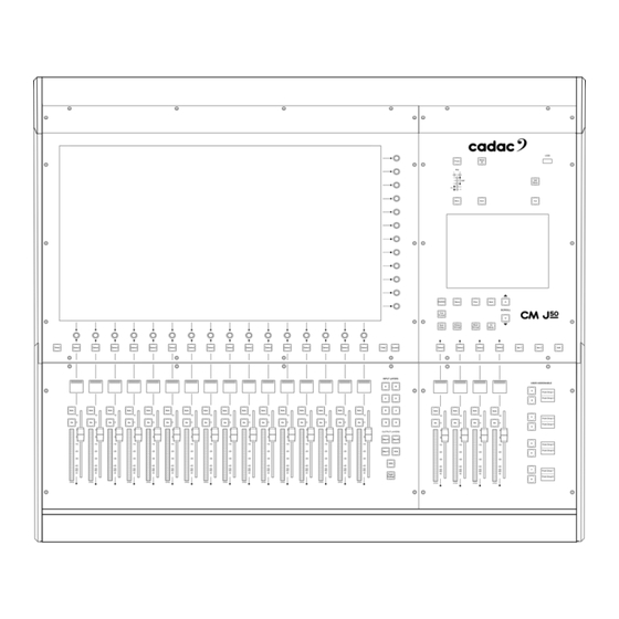
Page 22: Cm-J50 Console Hardware Controls
CM-J50 Console Hardware Controls Control Surface: 23.5” Screen and Main Fader Bank CM-J50_22-01-2024_Iss-1 Page. 22 / 129... - Page 23 1. Main Screen: A 23.5”, 16:9 high-definition touchscreen. The default display shows a block of 16 consecutively numbered channels; alternative sets of channels may be displayed using the hardware layer buttons - Input Layers [12] or Output Layers [13], or by setting a Go To button using one of the 8 dual layer User Assign [Part 2: 29] buttons, or by “swiping”...
- Page 24 5. Copy Button: Used in conjunction with the Select [3] buttons when copying channel settings from one channel to another. 6. Swap Button: By default, the input blocks of the channel strips are displayed at the top of the virtual channel strip and the pan blocks at the bottom. The lower encoders control pan by default, but pressing SWAP exchanges the on-screen positions of the input gain blocks and pan blocks and reassigns the lower encoders as the channel input gain/trim controls.
- Page 25 ‘Block Latching’: Press and hold one Solo button and press another Solo button while still pressing the first. This will solo the block of channels between the two buttons. Note: Press and hold of any Solo when other solos are in place will cancel itself and all other solos when released In use, the Solo button illuminates in a colour that is mode dependent.
- Page 26 displayed fall in between 16 “complete” layers, then the Output Layer buttons immediately above and below will both light up. Once a “complete” layer of 16 is shown, then only the relevant Layer button will be illuminated. 14. VCA button: Displays the VCA assignment page, and the faders become VCA masters. 2: VCA Assignment screen.
- Page 27 By pressing “BUS VCA” it will bring up the VCA setup page for the busses. Again, busses can be assigned to a VCA and the VCAs named: 4: Bus VCA Setup screen 15. GEQ button: Press this when an output bus is selected (with the Select [3] button illuminated) to access the CM-J50 ’s graphic equaliser function for that bus.
- Page 28 6: GEQ screen. The GEQ can be by passed by pressing ByPass 7: GEQ screen. The GEQ can be stored and recalled from the Settings Library CM-J50_22-01-2024_Iss-1 Page. 28 / 129...
- Page 29 16. Fader Follow button: When active, the Fader Follow Outputs function allows the operator to use the faders to control the bus send levels from the currently selected input channel. An input channel layer must be selected for Fader Follow Outputs to be available. The left-most channel in the visible set, and busses 1 to 16 will be selected by default: the Select [3] buttons select other channels, the left / right Scroll [26, 27] buttons allow navigation both up and down the busses.
- Page 30 9: GEQ and MONITOR FOLLOW Bus sends VCAs can also be accessed via this page. The members of each bus VCA remain the same as the normal VCA group membership, but the bus VCAs only attenuate the level of its members within the selected bus mix. Solo Follow sends each bus mix, when selected, to your monitors / headphones.
-
Page 31: Control Surface: 6.5" Screen And Master Section
Control Surface: 6.5” Screen and Master Section CM-J50_22-01-2024_Iss-1 Page. 31 / 129... - Page 32 1. Power button: This is a multi-function “soft” button for starting and closing the console surface. There is also a physical power switches on the rear of the console that shuts power off to the PSUs in the console. 2. Mute All button: Pressing this button will apply a ‘hard’ mute to all analogue outputs from the console.
- Page 33 12. FX button.: Quick access to the FX window. 13. Prev. button: Brings up the previous Cue. 14. Store button: Stores a Cue. 15. Update button: Updates the currently selected Cue (in the Cue List). 16. Cue P.view button: Allows an offline preview of a Cue and permits changes to be made to the Cue.
- Page 34 19. Mute Group button: Pressing this brings up the Mute Groups Setup page on the 23.5” screen. This allows the input channels to be assigned to any number of the eight Mute Groups. This is a toggle function, and a second press reverts to the previously display. 11: Mute Group setup screen.
- Page 35 22. Set 1 button: Brings up Set 1 of buttons defined by the user on the User Defined Button Setup screen to the hardware User Defined Button [29], with the function displayed on the OLED screen next to the button. 23.
- Page 36 30. LCR master fader: A 100 mm fader controlling the main stereo or LCR output. This is a VCA master fader controlling all three master output channels; the levels of the individual L, C and R legs may be controlled by the Mix Left, Mix Centre and Mix Right faders of the master channels which are accessed by swiping the display to below Output Channel 1 or above Input Channel 64.
-
Page 37: Cm-J50 Console Rear Panel
CM-J50 Console Rear Panel Rear Panel Connectors 1. Mains Inputs: Two switched IEC sockets for the dual internal power supplies. The unit is designed to run off one PSU, however it is recommended that the unit is run on both PSUs to ensure optimum load and heat management and adds PSU redundancy. - Page 38 interface – three RJ45 network connectors carrying 64 bi- ® ® 6. SoundGrid®: Waves SoundGrid directional channels of audio. The interface allows multitrack recording on an external computer ® ® ® or connected to a Waves MultiGrid server for the full range of external Waves FX plug-ins ®...
- Page 39 The default sample rate for the outputs is 48 kHz; this can be changed in the AES3 Configuration page on the Menu Screen to 44.1 kHz, 48 kHz and 96 kHz. 15: Access to the AES3 Configuration Screen 16: AES3 Configuration Screen CM-J50_22-01-2024_Iss-1 Page.
- Page 40 11. Inputs: 16 balanced “local” analogue audio inputs to the CM-J50, on XLR sockets. 17: Analogue Inputs on male XLRs 48 V LEDs: 16 red LEDs; illuminate when 48 V phantom power is enabled at the associated input connector. These may be the sources for any input channel or insert return in the same way as the remote stage rack inputs.
-
Page 41: Connecting The Hardware
Connecting the Hardware MegaCOMMS Cadac’s proprietary MegaCOMMS hi-speed data protocol is used to interconnect the console and stage rack(s). The control surface has four BNC sockets to provide the main system data interconnection, labelled IN (RX) A, OUT (TX) A and IN (RX) B, OUT (TX) B. The interconnections are also available on optical via 2 optical ports next to the BNC sockets. -
Page 42: System Connection Options
NOTE: You cannot use coaxial and fibre optic cables on the same MegaCOMMS port at the same time. One cable type must be selected for that port. One stage rack: Non-Redundant System using coaxial cables (or fibre optic) Cadac CM-J series Max Cable Run: Optical 2km... - Page 43 Two stage racks: Non-Redundant System using coaxial cables Cable Run ≤ 100m Cadac CM-J series SR series stage rack 2 Cable Run ≤ 100m SR series stage rack 1 One stage rack: Redundant System using coaxial cables Cadac CM-J series Cable Run ≤...
- Page 44 Console and two stage racks: Non-Redundant System using fibre optic cable Cable Run ≤ 2 km Cadac CM-J series SR series stage rack 2 Cable Run ≤ 2 km SR series stage rack 1 NOTE: With the system setup above MegaCOMMS PORT A on both stage racks MUST be connected to the console.
- Page 45 Console and daisy chaining two racks using coaxial cables SR series stage rack 2 Cadac CM-J series Cable run ≤ 100m Cable run ≤ 100m SR series stage rack 1 NOTE: With the system setup above MegaCOMMS PORT A on the first stage rack MUST be connected to the console.
- Page 46 NOTE: Only RG6 video cable suitable for 3G HD-SDI (High-Definition Serial Digital Interface) should be used for the Cadac MegaCOMMS connections. The cables should be terminated in BNC connectors of the appropriate type, and total system cable run should not exceed 100m (surface-to-stage rack or stage rack to stage rack as a snake).
-
Page 47: Word Clock
Word Clock The CM-J50 caters for digital audio I/O in the form of eight AES3 inputs and eight AES3 outputs, accessible on the rear of the control surface. 21: AES3 digital inputs and outputs on male and female XLRs The AES3 outputs have Sample Rate Converters (SRCs) and can operate at any frequency required by applying an external clock source to the WORD CLOCK IN connector. -
Page 48: Remote Stage Rack Connections
Remote Stage Rack Connections Audio Connections The stage racks provide the (non-local) audio inputs and outputs for the system and are intended to be located remotely from the control surface, typically stage-side. Audio equipment to be used at the FOH position can be connected to the control surface’s local I/O (when fitted) on the rear panel. -
Page 49: Routing
Some additional connectors will be required in all installations for channel or bus insert sends and returns, and for ‘B’ inputs to input channels. For further information regarding the stage racks please refer to the “Cadac Audio Stage Racks: CM- SR64 CM-SR40 CM-SR24 Hardware Overview” manual”... -
Page 50: Connector Details
Connector Details Analogue Inputs: 3-pin female XLR connectors. The inputs are electronically balanced and are suitable for connection of either microphones or line level sources. Input impedance is 1.2 kohms in Mic Mode, or 10 kohms in Line Mode, Mic or Line mode being selected from the assigned channel’s Input Gain panel. -
Page 51: Surface And Local I/O: Audio Connections
Surface and Local I/O: Audio Connections Analogue inputs: The connector and characteristics of the local analogue inputs are identical to those on the remote stage racks: Connection Screen Signal ‘hot’ (phase) Signal ‘cold’ (antiphase) Analogue outputs: The connector and characteristics of the local analogue outputs are identical to those on the remote stage racks: Connection Screen... - Page 52 AES3 digital outputs: Four AES3 digital audio outputs are available at the rear of the control surface on 3-pin XLR male connectors. The outputs are balanced, with a characteristic impedance of 110 ohms. Connections to these outputs should always be made using cable specifically designed for digital audio.
-
Page 53: Other Control Surface Audio I/O
Other Control Surface Audio I/O Headphones The stereo monitor signal is also available on two ¼” (6.35 mm) 3-pole (TRS) jack sockets for the connection to a pair of headphones. There are 2 sockets under the front armrest, on the left and right side, along with a volume attenuator for each headphone. -
Page 54: Principles Of Operation
Principles of Operation Switching the CM-J50 ON The Power button [1 in Control Surface Part 2] is a “soft” button for starting and powering-down the surface. When the surface is not operative, but connected to power and the rear switch is on, the button illuminates red. -
Page 55: Switching The Cm-J50 Off
Switching the CM-J50 OFF To shut the surface down, ‘short-press’ the Power [1 in Control Surface Part 2] button again, and a dialogue box will be displayed asking if the console should be shut-down (YES), or restart (Warm Start) while continuing to process audio or CANCEL. Selecting YES initiates a power-down sequence, ensuring that the computer is shut down correctly. -
Page 56: Touch Operation
Touch Operation This section of the manual describes the basic principles of screen navigation and parameter controls. All audio operations on the CM-J50 are performed using the touchscreen. The display shows sixteen consecutive virtual channel strips and includes the most important information about the channels’ configuration and parameters. -
Page 57: Exit
EXIT The EXIT button will, as the name implies, exit the current function on the screen. This will close the function - e.g. EQ or Dynamics – plus, it will remove all the mapping to the encoders for that function. 32: EXIT closes the function, or window, and removes any mapping to the encoders... -
Page 58: Layers
Layers The CM-J50 provides three methods of changing “layers” or going to channels. 1. Layer buttons: There are 8 Input Layer (A to H) buttons plus 3 Output layer (Bus A to Bus C) buttons which can be used to bring up either Input Layers or Output Layers in blocks of 16. The faders, OLED displays and the On, Solo and Select buttons always follow the on-screen channel strips selected by either the Input or Output Layers. - Page 59 2. User Assignable buttons: 1 to 8: These multi-function buttons are by default the masters for the CM-J50’s Mute Groups on 1 to 8. The User Assignable buttons can also be assigned to the Go To function. This gives quick access to any input or output channel. This will then bring up the selected channel followed by the 16 following channels.
- Page 60 The User Assign buttons can be reassigned to other functions via the User Define Button Setup screen, accessed via the Edit button. 35: USER DEFINE BUTTON SETUP screen 3. Swiping: A “swipe” action horizontally across the screen will shift the displayed set of channels by a number of channels proportional to the “length”...
-
Page 61: Channel Meters
Channel Meters The CM-J50 has 20 dual bar graph meters located in the fader bay and in the master section, one per fader. The source for each meter will always be the signal in its channel; the identity of this will be confirmed by the OLED immediately above. - Page 62 The default source for the bar graph meters is Post Fader, but this may be changed to Pre-Fader on the Menu screen’s Meter Options page. By default, the on-screen meters and the Bus Follow are both set to Pre-Fader. In addition to the fader bay meters, each channel strip - input or output - on the screen includes a small virtual bar graph - dual on stereo channels - complete with a 0 dB reference point.
-
Page 63: Channel Blocks
Channel Blocks Touching a channel block opens a virtual panel, or window, with all controls relevant to the block. Below are the channel blocks for the input channels. The same principle applies to the output channels. Mic Pre Compressor / Gate Bus Routing Channel... -
Page 64: Using The Mic Pre Block
Using the Mic Pre Block Touch the top of the input channel strip and the Input Gain Panel will open: Touching the “Mic Pre block” opens the Input Gain panel 40: Input Gain Panel CM-J50_22-01-2024_Iss-1 Page. 64 / 129... - Page 65 41: Input Gain Panel explained The Input Gain Panel provides access to: Channel Type: Mono, Linked or Stereo Channel Behaviour: Phantom Power (48V), Phase Reverse, Line (20 dB pad) Channel Source: A or B input Channel Assignment: Assign Input, Assign Direct, Assign Send or Assign Return Assign Direct can be set Insert, Pre EQ, Pre Fader or Post Fader Assign Send can be set Insert, Pre EQ, Pre Fader or Post Fader Assignment Parameters:...
- Page 66 42: Routing Panel When a channel is Assigned the Routing panel appears. This allows the selection of routing from: Local: 16 analogue inputs and 4 stereo AES inputs Rack 1: The number of channels available are depending on what unit is attached to MegaCOMMS port A.
- Page 67 If SR racks are connected, the clock for AES3 ports can be set on this page either at 96 kHz or 48 kHz. Options along the bottom of this panel also allow the unit to be cleared of all inputs or outputs routing or provide 1:1 routing.
-
Page 68: Using The Output Assign Block
Using the Output Assign Block Touch the top of the output channel strip and the Output Assign Panel will open: Touching the “Output Assign Block” opens the Output Assign panel 45: Output Assign Panel CM-J50_22-01-2024_Iss-1 Page. 68 / 129... - Page 69 46: Output Assign Panel explained This provides access to: Channel Type: Stereo, AUX, Group, Matrix Channel Assignment: Assign Input, Assign Direct, Assign Send or Assign Return Assign Direct can be set Insert, Pre EQ, Pre Fader or Post Fader Assign Send can be set Insert, Pre EQ, Pre Fader or Post Fader Assignment Parameters: Trim, Send Trim and Return Trim These functions automatically map themselves to the encoders...
- Page 70 47: Routing Panel When a channel is Assigned the Routing panel appears. This allows the selection of routing from: Local: 16 analogue inputs and 4 stereo AES inputs Rack 1: The number of channels available are depending on what unit is attached to MegaCOMMS port A.
- Page 71 If SR racks are connected, the clock for AES3 ports can be set on this page either at 96 kHz or 48 kHz. Options along the bottom of this panel also allow the unit to be cleared of all inputs or outputs routing or provide 1:1 routing.
-
Page 72: Using The Pan Block
Using the Pan Block Touch the bottom of the Input channel strip and the Pan Panel will open: 48: Touching the Pan Block will open the Panning options 49: The Pan Panel will appear showing LCR, LR, L, R and C. The panning is done by the encoder below the panel CM-J50_22-01-2024_Iss-1 Page. - Page 73 For a MONO channel the Pan Panel provides access to LCR routing: LCR: When centrally panned the signal is routed to the C bus. A press and turn of the encoder allows the pan depth to be adjusted. Routes the channel signal to the master output via the pan control, allowing stereo panning between the L and R busses Routes the channel signal to the L bus of the master output Routes the channel signal to the R bus of the master output...
- Page 74 Touch the bottom of the Bus strip and the Pan / Delay panel will open - two types of Pan / Delay Panel, depending on output type.: 50: The Pan / Delay Panel will appear showing LCR, LR, L, R and C, plus the Time Delay controls Pan / Delay Panel: It is possible to route to the LCR master bus from both Aux and Group output...
- Page 75 Time Delay: Sample-accurate time delay into the Aux, Group, Matrix or Master outputs can be inserted. Touching the OFF / ON button enables the delay, assigning the time control to the encoder. When the Pan Panel is closed, the encoder reverts to its Pan function.
-
Page 76: Using The Encoders
Using the Encoders The main screen has 28 rotary encoders around its perimeter – 16 horizontally below the screen and 12 vertically to the right of the screen. The encoders also have a push and push / hold function for certain operations. - Page 77 Touching the direction arrow will put the EQ on the vertical - see below 53: EQ - The EQ GUI is on the horizontal and the functions are mapped to the bottom 16 encoders. 54: EQ - The GUI is now on the vertical and the functions are now mapped to the 12 vertical encoders on the right. The EQ GUI can also be scrolled up or down by touching and dragging the blank areas found in between the EQ graphs.
- Page 78 55: Dynamic EQ when EQ is on the horizontal: When Dynamic EQ is selected, by pressing Dynamic and then the bands that dynamic EQ will operate on, the controls for the Dynamic EQ will appear next to the vertical encoders. The control for rest of EQ will remain active on the horizontal set of encoders.
-
Page 79: Bus Sends
Master L&R or a Matrix, and the Master L&R can also be routed to any Matrix Bus. It is worth noting that Cadac employs a comprehensive latency management system, meaning that routing through the console will not alter the phase alignment of the outputs. An example would be to route an Input Direct to a Matrix output, as well as routing the same Input to Group, then routing the Group to the Master L&R and then route the Master L&R to the same Matrix. -
Page 80: Keyboard
Keyboard The CM-J50 allows the naming of a number of functions e.g., Inputs, Busses, VCAs and User Layers. This can be done via accessing the required Settings screen (or for a bus or channel by double tapping the digital write-on strip and for a VCA by tapping a VCA). Once in the Settings screen select the Input / Output / VCA etc for renaming and then press Rename and this will bring up the virtual QWERTY keyboard on the screen. -
Page 81: User Layers
User Layers The CM-J50 also allows input channels, busses and VCAs to be pinned / stuck to the screen in any combination in a User Layer or custom layer. These will remain on the screen - with the associated fader (s) also pinned in the fader tray - whilst the remainder of the channels can be navigated as normal (unless all 16 channels are used). - Page 82 Any combination of Inputs, Busses, VCAs and Monitor functions can be allocated to a layer. The User Layer can be saved, named, coloured coded and pinned to either side - left or right - of the screen and be allocated to a User Assign button. 62: User Define Layer Setup: Select Input Channels, then select the input to be added to the customer layer 63: User Define Layer Setup: Select Monitors,...
-
Page 83: Effects
Effects There are 16-stereo or mono on-board effects units including various types of reverbs, delay and modulation effects. The 16-stereo effect “slots”, each with reverb, modulation, and delay elements, can be used simultaneously and freely configured by the user. Pressing the FX Configuration window... - Page 84 In the screen below the 3 elements within each effect slot can be arranged in either series or parallel, and in any order, by simply ‘dragging and dropping’ the required component. By default, the effects are stereo units, however by pressing Change to Mono deselects the stereo mode and reconfigures the effects to dual mono, allowing the Left and Right to be used as separate units.
-
Page 85: Geq
All output busses feature 4-band fully parametric EQ, variable HPF and LPF plus a 1/3 octave GEQ. By pressing the GEQ [15: Control Surface Part 1] button - to the left of the screen - when the busses are selected, the GEQ screen will open. This shows 31 bands in BYPASS mode (press BYPASS to take it out of bypass) on the screen. - Page 86 All parametric and graphic EQ’s can be used simultaneously, without any concern about available processing power or tonality compromise. Additional features include GEQ in / out, an “instant flat” switch plus a bypass function for individual GEQ filters. CM-J50_22-01-2024_Iss-1 Page. 86 / 129...
-
Page 87: Control Screen Menus
Control Screen Menus During a performance, the Control Screen Menu will normally be used to display the Cue list. Pressing the Cue List [9 Control Screen Part 2] button, will bring up the Cue list. 67: Control Screen displaying the Cue list 68: Menu Screen displaying the Cue options displayed by double taping a Cue or pressing the Store button CM-J50_22-01-2024_Iss-1... - Page 88 The Menu Screen Home page provides five menus – Projects, Cues, Configuration, User Options and Settings. Touching any of the tabs opens a further menu at the side. Projects menu is effectively part of the CM-J50’s automation system: it enables file creation and management functions and is used when starting a new project or loading a previously stored one.
- Page 89 Configuration menu is used to configure the basic architecture of the console. 71: Menu Screen displaying the Configuration menu • Channel Settings page opens on the screen and is used to define Input Channels as Mono, Stereo, or Linked, and to name or move the channels. •...
- Page 90 User Options menu provides access to Recall Safes, User Layers set up screen, the User Assign button setup screen and Metering configuration. 72: Menu Screen displaying the User Options menu • Recall Safes menu provides the options of taking the I/O Patching, Channels Modes, Channel Head Amp, I/O Patching Outputs, Bus Modes, Outputs, Brightness, VCA Fader and VCA Mutes globally out of the automation.
- Page 91 Settings menu allows access to a number of parameters of the console including controls for the brightness of the screen and LEDs, plus this is where the screen and console can be locked. It also provides access to the information regarding the console - serial number, software version along with System that monitors the power status of the console.
-
Page 92: System Functions
System Functions Waves® SoundGrid® Interface ® ® Waves SoundGrid is a proprietary high-speed digital audio transport protocol with a capacity of 64 bi- ® directional channels at 96 kHz. The CM-J50 is fitted with a SoundGrid interface card, accessible on the rear panel via three RJ45 network connectors. - Page 93 Input Output Waves Local IO Waves Local IO Waves 1 Waves 1 Waves 2 Waves 2 Waves 3 Waves 3 Waves 4 Waves 4 Waves 5 Waves 5 Waves 6 Waves 6 Waves 7 Waves 7 Waves 8 Waves 8 Waves 9 Waves 9 Waves 10...
-
Page 94: Usb Ports
Ethernet ports for purposes of adding a wireless network router when using the iPad. It can also be used to connect to an internet connection for emailing the console’s logs back to Cadac. Cat-6 cable suitable for 1000base-T use is recommended for network connections. -
Page 95: Ipad App - Cm-Remote
App – CM-Remote Cadac’s iPad App – CM-Remote – provides the perfect solution for controlling wirelessly the key functions of the CM-J series of audio mixing consoles via an iPad or iPads. The App can be found on the Apple App Store, search for CM-Remote. - Page 96 77: CM-Remote iPad: MUTE Groups 78: CM-Remote iPad: Compressor 79: CM-Remote iPad: GEQ CM-J50_22-01-2024_Iss-1 Page. 96 / 129...
-
Page 97: Connecting A Wi-Fi Router
Connecting a Wi-Fi Router To connect the console to the iPad the console needs to run Remote Connector upon start-up. The Remote Connector must be selected on the “Cadac Console Configurator” screen during console start-up. When the Loader screen appears press “Console Type”: 80: Loader Screen This will bring up the Console Configurator screen. -
Page 98: Network Selection
Console connection to a Wi-Fi router Note: Use the port labelled Network. The three ports on the Waves card will not work with a wireless router. Wireless Router Ethernet Cable Network Selection The console now needs to be configured to use the Network Ethernet port that is now connected to the wireless router. - Page 99 This will bring up the “Remote Settings” page, select “Network Port”: 83: Remote Connector Settings Page This will bring up the “Network Setup” screen: 84: Network Setup Menu This screen displays a list of all Ethernet network adapters on the console, this will vary depending on the console’s configuration.
-
Page 100: Remote Connector Settings
85: Network Setup Menu The console will now have access to the Ethernet Port with the wireless router attached. Remote Connector Settings For security reasons, the console must be able to control access of any iPads that are attempting to connect to it. - Page 101 This will bring up the “Remote Client Access” page: 87: Remote Client Access Screen When the “Remote” is flashing red, select the iPad trying to connect and press “Remember Me”. 88: Remote Client Access Screen The “Remote Client Access” screen also allows the console to remember an individual iPad and allow it to connect in the future without having to repeat the authentication process.
-
Page 102: Remote Connector Status
Remote Connector Status The Remote Connector Status screen is accessed via the central menu on “Remote Connector Settings” page. 89: Remote Client Access Screen This screen indicates the status of the Remote Connector, the status of the network adapter and the list of connected clients with details. -
Page 103: Offline Editor
Offline Editor The Cadac CM-Editor allows console Show files to be created and edited remotely on a Windows PC, and then saved and loaded on to the console via a USB drive. The latest version of the CM-Editor can be downloaded from the Cadac website www.cadac-sound.com. - Page 104 93: CM-Editor: The Control Screen window is accessed by selecting the Menu button at the top left of the displayed. This gives access to the menu structure that is found on the console’s 6.5” physical displayed, along with the Back and Cue buttons. 94: CM-Editor: At the top of the screen Project, Show and Cue information is displayed, along with the Time and the stage rack information –...
- Page 105 95: CM-Editor: This displays the Go To function A show can be created and saved in the same way as it would be on the console. The Show file can then be exported to a USB drive and imported on to the console via one of its four USB ports. Show files can also be exported from the consoles, edited on the CM-Editor, and imported to the console, or created on the CM-Editor and imported on to the console.
-
Page 106: Console Configuration: Modes / Configuration
Console Configuration: Modes / Configuration To change the console’s mode / configuration it can be done through the “Cadac Console Configurator” screen which is accessed via the Loader screen during console start-up. When the Loader screen appears press “Console Type”: 97: Loader Screen This will bring up the Console Configurator screen. -
Page 107: Side Car
Side Car Side Car configuration allows up to two consoles to be attached to the primary console and act as side cars to extend the work surface controls of the primary console. This does NOT increase channel count, just the control surface. The MegaCOMMS connection to stage racks is made via the primary console as this has the active mix engine. - Page 108 When the Loader screen (purple screen) appears on the Side Car Console (s) on start-up, press “Side Car A” (and “Side Car B” on the second side car console) to bring up the Console Configurator window. 99: Side Car A This will then bring up the Select Network Port List window.
- Page 109 This will then bring up the CM Console / Ecomixer ID window. Enter the console’s Ecomixer ID (the 4- digit Ecomixer code can be found on a label on the rear of the console, alternatively it can be found in the About section on the console) of the proposed Side Car (A / B).
- Page 110 Now press “Apply”: 103: Apply Completely power down all consoles, and then restart all consoles. The consoles are now set-up for console side car configuration. CM-J50_22-01-2024_Iss-1 Page. 110 / 129...
-
Page 111: Mirroring
Mirroring In Console Mirroring configuration, it allows a second (Follow) console to mirror, in real time, the status of the primary (Lead) console allowing for total console redundancy. NOTE: If the primary / Lead console was to ever to fail, the MegaCOMMS connectors would have to be manually disconnected from the primary / Lead console and connected to the secondary / Follow console for the audio to continue. - Page 112 Lead Console Power down and reboot the Lead console. When the Loader screen (purple screen) appears on the Lead console (primary console) on start-up, press “Console Type” to bring up the Console Configurator window. Then press “Lead Mirror Mode”: 104: Lead Mirror Mode This will then bring up the Select Network Port List window.
- Page 113 This will then bring up the Ecomixer ID window. Enter the Follow console’s Ecomixer ID (the 4-digit Ecomixer code can be found on a label on the rear of the console, alternatively it can be found in the About section on the console). Then “Exit” this window: 106: Ecomixer ID window All available consoles will be show in the list below.
- Page 114 Now press “Apply”: 108: Apply CM-J50_22-01-2024_Iss-1 Page. 114 / 129...
- Page 115 Follow Console Power down and reboot Follow console. When the Loader screen (purple screen) appears on the Follow console (secondary console) on start-up, press “Console Type” to bring up the Console Configurator window. Then press “Follow Mirror Mode”: 109: Follow Mirror Mode This will then bring up the Select Network Port List window.
- Page 116 This will then bring up the CM Console / Ecomixer ID window. Enter the Lead console’s Ecomixer ID (the 4-digit Ecomixer code can be found on a label on the rear of the console, alternatively it can be found in the About section on the console). Then “Exit” this window: 111: Ecomixer ID window All available consoles will now be show in the list below.
- Page 117 Now press “Apply”: 113: Apply Now completely power down all consoles, and then restart all consoles. The consoles are now set-up for console mirroring. CM-J50_22-01-2024_Iss-1 Page. 117 / 129...
-
Page 118: Normal
Normal If the console has had its configuration / mode changed - e.g. set-up for Side Car or Console Mirroring - it will need to be reset to standard / normal Mode. When the Loader screen (purple screen) appears during start up, press “Console Type” to bring up the Console Configurator window. -
Page 119: Bus Configuration
Bus Configuration The console can run in two bus configurations; Front of House mode with 48 configurable busses plus LCR (a total of 56 busses), or in Monitor Mode which allows 54 configurable busses – the LCR busses have been added to the configurable bus capability – (a total of 56 busses). NOTE: The console by default runs in Front of House mode. -
Page 120: Remote Connector
Remote Connector To connect the console to the iPad the console needs to run in Remote Connector mode. See section “iPad App – CM-Remote” for further information and how to set-up the console to run with an iPad. CM-J50_22-01-2024_Iss-1 Page. 120 / 129... -
Page 121: Command Centre
1. The status information window. This displays information relevant to the function that has been selected. Note: There is an Expert View of this page – but this should only be accessed by approved Cadac service personnel. The “Novice” setup screen will allow for the majority of the maintenance tasks to be performed. - Page 122 This requires the console to be powered off and restarted for the firmware update to start. Disk Scan: Cadac service advice required for this process. This is typically pressed following an event in which the console has failed to shut down properly and allows the console to check for issues and run automatic repairs.
- Page 123 Clear Caches: Removes all the caches and temporary files stored by the console. This can help with speeding up the console if the console is slow to respond. Touch Screen Calibration: Allows the touch screens to be recalibrated should the screen’s touch become inaccurate.
-
Page 124: Updating Software
This can be done by inserting a USB key containing the latest software. Download the latest version from www.cadac-sound.com (software is on the Support / Software Download page), then unzip the software on the root of a clean / empty USB key. Then insert the key into one of the four USB ports on the console and then follow the on-screen instructions. -
Page 125: Appendix
16 x XLR Mic Inputs (inc 48 V, PAD and 1 dB gai n steps), 8 x XLR Balanced outputs, 4 x XLR AES/EBU inputs and 4 x XLR AES/EBU outputs Comms 2 x Cadac MegaCOMMS on: 4 x BNC 2 x Duplex optical LC ports CM-J50_22-01-2024_Iss-1... - Page 126 Audio S pecification Sample Rate 96 kHz Processing Delay Sub 0.4 millisecond latency through compl ete signal chain Internal Processing 40-bit floating point ADC/DAC 24-bit Frequency Response 20 Hz to 44 kHz + 0.5 / -1.5 dB THD+N better than 0.005% @unity gain, 10 dB input at 1 kHz Channel Separation better than 90 dB <...
-
Page 127: Dimensions
Dimensions Net Weight 39.5 kgs / 87.08 lbs * *Approx. weight out of flight case CM-J50_22-01-2024_Iss-1 Page. 127 / 129... -
Page 128: Notes
Notes: CM-J50_22-01-2024_Iss-1 Page. 128 / 129... - Page 129 Cadac whether mechanical or electronic, without the written permission of Cadac. One New Street Due to Cadac’s policy of continual Luton improvement Cadac reserves the right to Bedfordshire alter features, appearance and specifications without notice.
Need help?
Do you have a question about the C Series and is the answer not in the manual?
Questions and answers