Table of Contents
Advertisement
Quick Links
Advertisement
Table of Contents

Related Manuals for Cadac B-Type


Summary of Contents for Cadac B-Type
- Page 1 &g8;2' Audio Mixing Console -056#..#6+10#n#95'4#1#07#.
- Page 2 While every effort has been taken to ensure the accuracy of the contents in this manual, CADAC Audio Mixing Consoles are subject to con- tinuous development, hence the information in this manual may not reflect the latest product updates.
-
Page 3: Table Of Contents
10.2 Listen Module 7891 - rear panel ..........10-6 2VF/#&RPPV#)#3)/#PRGXOH################################################ ::8;#+007\SH#JURXSV, 1111111111111111111111111111111111111111 #4404 11.1 Osc, Comms & PFL module 7758 - front panel ......11-2 11.2 Osc, Comms & PFL Module 7758 - rear panel ......11-9 Revision B2005-2 B-Type... - Page 4 Table of Contents 2VF/#&RPPV#)#3)/#PRGXOH################################################## :968#+)07\SH#JURXSV,# 4504 12.1 Osc, Comms & PFL module 7635 - front panel ......12-2 12.2 Osc, Comms & PFL Module 7635 - rear panel ......12-7 $SSHQGLFHV11111111111111111111111111111111111111111111111111111111#$330, ,QGH[111111111111111111111111111111111111111111111111111111111111111111 #,1'0, B-Type Revision B2005-2...
- Page 5 Air flow required for safe operation may otherwise be restricted. Where the console is to be operated in its flight-case, then this must be located in such a way that it allows for proper ventilation. 6HUYLFH Refer servicing to qualified technical personnel only. Revision B2005-2 B-Type...
- Page 6 General Precautions B-Type Revision B2005-2...
- Page 7 The B-Type is designed to meet the needs of modern live broadcast programming - offering modularity with easy upgradeability, protecting your investment for the future.
- Page 8 Introduction B-Type Revision B2005-2...
-
Page 9: &Rqqhfwlqj#Wkh#Pl
SELECTOR FRAME TO FRAME FIG 1-1. B-Type frame rear connections. The connections on the B-Type console rear frame include the following (from left to right): Audio Bus - frame to frame, up to 4 frames can be connected. Data Bus - frame to frame... - Page 10 ‘load’ is shared between the “main” and “backup” PSU’s. If a fault occurs in one of the power units (causing it to ‘shut-down’), the remaining power unit will power the con- sole. For smaller B-Type consoles (consuming no more than 44A), it is possible to use the 8400 PSU. See 1.3.7 8400 switch-mode power supply unit.
- Page 11 41615 $&#SRZHU#UHTXLUHPHQWV CADAC power supply units are designed to run from a minimum of 208 V up to a maximum of 260V, 50/60Hz a.c. In many parts of the world the normal a.c. single- phase supply is 100-127V, this means that the CADAC power supply units must be connected across two of the phases in the three-phase a.c.
- Page 12 ;353#´469µ#VZLWFK0PRGH#SRZHU#VXSSO\#XQLW The older version of 8020 +13v/48v unit is based on one ADVANCE F20006 ‘power- block’, with additional circuitry as shown on CADAC drawing number C3.8016. The new version is based on PowerOne PSUs (serial number 34949 onwards). The a.c. input is connected to the PSU via a 3-core cable, CMA reference 3183TQ –...
- Page 13 (the voltage between one of the phases and neutral) exceeds 127V. The installation should be carried out by a qualified electrician who understands your partic- ular installation and the local safety and wiring regulations. Revision B2005-2 B-Type...
- Page 14 6. Connect a PSU cable between the “SYSTEM 2" rack and the “PSU SYSTEM 2" connector on the EXTENSION FRAME 1. 7. Repeat procedures 5 and 6 for EXTENSION FRAME 2 (a 3 frame console). 368#6<67(0#4#+“4;9, 368#6<67(0#5#+“4;9, 368#6<67(0#4#+7;92.469, 368#6<67(0#5#+7;92.469, FIG 1-6. Power connections B-Type Revision B2005-2...
- Page 15 CONNECTED AT BOTH ENDS FIG 1-7. Remote start of 8019/8020 up to serial number 34950 Great care must be taken with the wiring of the switch(es) to ensure that no short-cir- cuits can occur between any two power supply units. Revision B2005-2 B-Type...
- Page 16 FIG 1-8. Remote start of 8019 PSU (from serial number 34950) VIEW FROM SOLDER CUP/TAG SIDE “START” MOMENTARY PUSH BUTTON 300R OVER TEMPERATURE 300R POWER FAILURE FIG 1-9. Remote start of 8020 PSU (from serial number 34950) B-Type Revision B2005-2...
- Page 17 4161: ;733#VZLWFK0PRGH#SRZHU#VXSSO\#XQLW FIG 1-10. 8400 power supply unit. CADAC 8400 switch-mode power supply units are designed to run from a minimum of 208V up to a maximum of 260V a.c, 50/60Hz. The 8400 is rated thus +13V@92A, ±18V@44A and 48V@5A.
- Page 18 PSU 8400 with multiple switches. Great care must be taken when wiring the switch(es) to ensure that no short-circuits can occur between any two power supply units. FIG 1-12. Remote start of PSU 8400 with a single switch B-Type Revision B2005-2...
- Page 19 This cable has a male XLR 3-pin connector on one end and a female XLR 3- pin on the other end. Connect one end of the “Oscillator/Communications” module’s “PFL TO HP” connector and the other end to the rear frame connector labelled Revision B2005-2 B-Type...
- Page 20 Connect one end of the “PSU IND” cable to the “PSU IND” 15-way male D-sub connector on the CCM. Connect the other end of the “PSU IND” cable to the “PSU IND” 15-way female D-sub connector on the rear console frame adjacent to the two multi-pin power input connectors. B-Type Revision B2005-2...
- Page 21 Power cannot be delivered from the input modules to the 48V bus if the copper bar is missing, because the screened microphone input cables will not be terminated. It will also cause damage to the motor faders. Revision B2005-2 B-Type...
- Page 22 20 MB free hard disk space PS/2 keyboard (older 5-pin DIN keyboard can be used with adapter) PS/2 mouse or pointing device (9-pin’D’-serial devices cannot be used) PS/2 keyboard (older 5-pin DIN keyboard can be used with adapter) B-Type Revision B2005-2...
- Page 23 PC interface. These connectors should be connected directly into a computer. It is also possible to connect the RJ45 sockets to a hub. For details about this, contact CADAC technical support. FIG 1-18. Séance front panel connections - BNC and RJ45 0RXVH .H\ERDUG...
- Page 24 4181< )DVW#FRSSHU#FRPPXQLFDWLRQV CADAC’s 15 way “fast copper communications” cables are used to connect between the Séance box’s fast comms connectors and the CCM. The cable plugged into Fast comms PC1 on the Séance box must be connected to PC1 on the CCM.
- Page 25 1. CCM PC1 to Séance box PC1. 2. CCM PC2 to Séance box PC2. 3. CCM KEYS to Séance box KEYS. Details on Seance set-up can be found in the Seance Interface 7975 User & Installa- tion manual. Revision B2005-2 B-Type...
- Page 26 Two serial port configurations are in common use with 9 way or 25 way 'D-Type' con- nectors. The two computers will only “track” each others’ Cue position if the SAM tracking fea- ture has been enabled, see the SAM manual for details. B-Type Revision B2005-2...
- Page 27 FROM PFL NEXT LIGHTS AUDIO BUS DATA BUS FRAME AUDIO BUS COMMS TO CCM PSU INDICATOR FRAME - 0V FRAME TO FRAME SELECTOR FRAME TO FRAME 7R#QH[W#IUDPH FIG 1-21. Connecting the main frame facilities from modules to frame. Revision B2005-2 B-Type...
- Page 28 41:14 6\VWHP#SRZHU0XS#SURFHGXUH CADAC consoles are designed to work continuously with two power supply systems - ‘main’ and ‘backup’. The ‘main’ power supply pair (1 off ‘18v’ unit and 1 off 13V/48V unit) are designated ‘System 1’. The ‘backup’ power supply pair (1 off ‘18V’ unit and 1 off 13V/48V unit) are designated ‘System 2’.
-
Page 29: &Hqwudo#&Rqwuro#0Rgxoh#:;<9 1111111111111111111111111111111 #504
&&0#)URQW#3DQHO#VZLWFKHV#DQG#GLVSOD\V Please refer to fig 2-1 on page 2-2 for the location of the switches and displays on the B-Type CCM front panel issue 7896 described on the next page. 0DVWHU#0XWHV Four separate switches to globally mute the channels, subgroups, matrix groups and aux groups. - Page 30 Central Control Module 7896 FIG 1-1. B-Type CCM control panel. B-Type Revision B2005-2...
- Page 31 READY and WRITE modes. Therefore, editing of a recorded sequence can be performed for as long as the fader knob is actually touched and the fader remains in the READY mode. Revision B2005-2 B-Type...
- Page 32 In normal operating conditions the display will show one of the following: CUE number, or Current Memory number, or “cadac ‘B-Type’ “ if no cue or memory is selected The display is also used for system messages via the [err] button and to traverse the various menus for testing, mapping, etc.
- Page 33 To put a small number of motor faders in READY mode: a) Press the “SET READY” switch. b) Touch each fader knob that is to be recorded and make fader movement required. c) Press the “SET READY” switch (to cancel the function). Revision B2005-2 B-Type...
- Page 34 Central Control Module 7896 &&0#UHDU#SDQHO#FRQQHFWRUV Please refer to figure 2-3 for the location of the connectors on the B-Type CCM mod- ule rear panel described below. )DVW#&RSSHU#&RPPXQLFDWLRQV#,22 Two cables provide the “fast copper” data link between the CCM and up to two IBM®...
- Page 35 OPEN contact normally CLOSED contact MOVING contact (wiper) normally OPEN contact normally CLOSED contact MOVING contact (wiper) normally OPEN contact normally CLOSED contact MOVING contact (wiper) normally OPEN contact normally closed contact MOVING contact (wiper) normally OPEN contact Revision B2005-2 B-Type...
- Page 36 Assuming all is found to be well, the display then changes to “cadac B-Type” and the CCM is ready to be used. This is one of the “root” displays, and it is always possible to get back to this point by pressing the [Esc] key (it may be necessary to press [Esc] several times).
- Page 37 If the Cue number does not exist, the CCM display will show the error prompt, “non- existent cue” and the PC will show the error as “Cue n does not exist”. Press [ ↵] or [Esc] to continue. Revision B2005-2 B-Type...
- Page 38 Check relays and indication of events Check communications busses Test Fdr Comms Show Time Show real-time clock Show Date Show real-time clock and date View Error Log Look through the last recorded errors Clear Error Log Clear the error log B-Type Revision B2005-2...
-
Page 39: The System Setup Menu
Each Map is stored in non-volatile memory within the CCM. Map- ping operations should only need to be performed if the layout of the modules within the frame have been changed. A new console is always mapped by CADAC before it leaves the factory. - Page 40 The left and right arrow keys may be used to select each fader in turn, group 1 through 16, then channel 1 upwards. The numbers displayed after the colon repre- sent the raw fader data. If you encounter difficulties, please contact CADAC. B-Type...
- Page 41 Press [↵], followed by the Down Arrow button, until the display shows “ Test Comms? ” Press [↵ ↵ ↵ ↵ ]. The display shows “Comms busses OK” for a few seconds before returning to “ Test Comms?” Revision B2005-2 B-Type...
- Page 42 Press [↵], followed by the Down Arrow button, until the display shows “ Clear Error Log? ” Press [↵ ↵ ↵ ↵ ]. The log is cleared and the event is entered in the Error log. This test automatically returns to the system menu. B-Type Revision B2005-2...
- Page 43 Press the [Sys] key to use the System Setup menu. Press the [↑] or [↓] cursor keys until “User Setup ?” appears in the CCM display. Select the sub-menu by pressing [↵]. The CCM display will respond with ³8VHU#6HWXS #### ⇑⇓ ³1 Revision B2005-2 B-Type...
- Page 44 MIDI O/P Port Enable switches is set “off”. Press the [Sys] key to use the System Setup menu. Press the [↑] or [↓] cursor keys until “User Setup?” appears in the CCM display. B-Type Revision B2005-2...
- Page 45 *URXS0/LQN#21 In Group-Link mode, the DC master faders can “move” channel faders. AUX from VCA does not have the same meaning as in a non-motor fader system. When AUX VCA is not selected on a channel fader: Revision B2005-2 B-Type...
- Page 46 “revert” may be set Function Off RECORD Function enabled when recording a dynamic REC/PLAY Function enabled when recording or playing back a dynamic ALWAYS Function always enabled The option ALWAYS is primarily intended for test purposes. B-Type Revision B2005-2...
- Page 47 Enter. 3&#&RPPV#(UURU If the B-Type is used without a PC, this function disables the “ERR” button and pre- vents it from flashing because of missing Comms. There are two modes; “Hard” and “Soft”. Hard mode will cause the “ERR” button to flash when Comms are missing (when a PC and a CCM are used) and Soft mode will cause the “ERR”...
- Page 48 2-20 Central Control Module 7896 B-Type Revision B2005-2...
-
Page 49: ,Qsxw#&Kdqqho#Prgxoh#::4; 111111111111111111111111111111111 #604
±18dB cut and boost, variable frequency and Q. There are four EQ bands. The normal PFL and MUTE switches are situated near the fader section of the mod- ule, above and below the ‘DC Group” display. Following pages describe the input channel module 7718 in detail. Revision B2005-2 B-Type... - Page 50 Input Channel module 7718 ,QSXW#&KDQQHO#PRGXOH#::4;#0#IURQW#SDQHO 3.1.2 -20dB Pad 3.1.1 Input Gain 3.1.3 Phase Change 3.1.4 48V Phantom Power 3.1.6 Input Amplifier PFL 3.1.5 OSC/PNG Select 3.1.7 Auxiliary sends B-Type Revision B2005-2...
- Page 51 CCM (see 2 Central Control Module 7896). E.g. If Auxiliary 1 is selected ‘STEREO’ on the CCM, the “SET” LED in the AUX1 section on all input channels will illuminate and all AUX1 sections are stereo sends. Revision B2005-2 B-Type...
- Page 52 1.2kHz to 35kHz. The High Pass filter has an in/out switch with a variable frequency control 14Hz to 400Hz. 614143 (4#,12287#6ZLWFK#+SURJUDPPDEOH, The “EQ IN” switch (in the HP/LP section) simply switches the EQ in or out of circuit. B-Type Revision B2005-2...
- Page 53 INSERT is not selected, the signal is passed directly from the EQ section to the fader. Select INS to divert the channel audio signal to an external device and have the pro- cessed signal inserted into the signal path. Revision B2005-2 B-Type...
- Page 54 A PFL switch is included in each channel to allow the operator to instantaneously monitor the audio signal in the channel, pre fader. 61414; ¶'&#*URXS#'LVSOD\#+SURJUDPPDEOH, A seven segment display shows which DC Group Master the channel is currently selected to. B-Type Revision B2005-2...
- Page 55 The Fader has its local VCA MUTE set ON. The fader is being controlled by a DC Master fader set fully OFF (at infinity) The fader is being controlled by a DC Master fader with its local VCA MUTE set Revision B2005-2 B-Type...
- Page 56 NOTE: Pin 1 on the XLR connec- tors and the ‘sleeve’ connection on the jack sockets are con- nected to FRAME. This is to ensure that the console can comply with the Electromag- netic compatibility (EMC) direc- tive. B-Type Revision B2005-2...
-
Page 57: ,Qsxw#&Kdqqho#Prgxoh#:;;< 111111111111111111111111111111111 #704
EQ-bands. The equalizer can be switched pre or post the INSERT point. The normal PFL and MUTE switches are situated near the fader section of the mod- ule, above and below the ‘DC Group’ display. Following pages describes the input channel module 7889 in detail. Revision B2005-2 B-Type... - Page 58 4.1.15 Direct O/P Pre-EQ 4.1.16 Direct O/P Level 4.1.17 Direct O/P Post-Fader 4.1.18 Sub Group Switches 4.1.19 Pan Insert 4.1.20 Pan Pot 4.1.21 Aux Send Pre-Fader 4.1.22 Aux Send Stereo Indicator 4.1.23 Aux Send ON/OFF 4.1.24 Aux Send Level Control B-Type Revision B2005-2...
- Page 59 7141< ,QSXW#5#¶3$'·#,QVHUW Press the “-20” button to insert a 20dB pad in series with the input amplifier. 714143 ,QSXW#5#3KDQWRP#3RZHU#RQ2RII Press the “48V” button to connect phantom power to the input line. Revision B2005-2 B-Type...
- Page 60 This switch is programmable and its condition is recorded as part of the console sta- tus. 714153 3DQ#3RW When the Pan Insert switch is selected, the Pan Pot allows you to position the chan- nel signal relative to any ‘odd’ and ‘even’ pair of Sub Groups. B-Type Revision B2005-2...
- Page 61 (either side of the centre frequency) have the boost or cut applied. As the ‘Q’ value is increased, the bandwidth is reduced so that a very much smaller range of frequen- cies have the boost or cut applied. Revision B2005-2 B-Type...
- Page 62 (either side of the centre frequency) have the boost or cut applied. As the ‘Q’ value is increased, the bandwidth is reduced so that a very much smaller range of frequen- cies have the boost or cut applied. B-Type Revision B2005-2...
- Page 63 ‘in’. This switch is programmable and its condition is recorded as part of the console status. 71416; +LJK#3DVV#ILOWHU#LQ2RXW Press to insert the high pass filter.The LED is illuminated when the high pass filter is ‘in’. This switch is programmable and its condition is recorded as part of the console status. Revision B2005-2 B-Type...
- Page 64 4.1.52 20 segment LED Meter 4.1.54 Fader OPEN LED 71416< /RZ#3DVV#)LOWHU#)UHTXHQF\ Variable frequency control for the low pass filter, giving a frequency range of 1.25 kHz to 35 kHz.This is a “second-order” filter with a slope of -12dBu per octave. B-Type Revision B2005-2...
- Page 65 This is the main PFL button for ’monitoring’ the audio signal in the channel. 714179 '&#*URXS#VHOHFWLRQ Press the “+” switch to increment the DC Master Group number or the “-” switch to decrement the DC Master Group number. Revision B2005-2 B-Type...
- Page 66 The 20 segment LED meter continuously monitors the signal level in the channel, pre-fader, unless the “MTR DIR O/P” switch is pressed (see 4.1.14). When the “MTR DIR O/P” switch is pressed, the meter monitors the level of the channel’s direct out- put circuit. B-Type Revision B2005-2...
- Page 67 The fader has its local VCA MUTE set ON The fader is being controlled by a DC Master fader set fully OFF (at infinity). The fader is being controlled by a DC Master fader with its local VCA MUTE set Revision B2005-2 B-Type...
- Page 68 3-32 connector. NOTE: Pin 1 on XLR connectors and the ‘sleeve’ connections on the jack sock- ets are connected to the FRAME. This is to ensure that the console can comply with the Electric Compatibility (EMC) directive. B-Type Revision B2005-2...
-
Page 69: 6Whuhr#,Qsxw#Prgxoh#::94 11111111111111111111111111111111111 #804
The Stereo Input Module 7761 has eight stereo inputs.CADAC’s low-noise input amplifier is used in this module as well as in every other B-Type input module. The gain for each channel is controlled by one knob in segments of five dB in the range 0- 60dB. - Page 70 5.1.7 Left Input Phase Reverse 5.1.14 Right Input Phase Reverse 5.1.15 Oscillator Routing Right 5.1.8 Oscillator Routing Left 5.1.16 Right Input PFL 5.1.9 Left Input PFL 5.1.17 Right Input Routing 5.1.10 Left Input Routing 5.1.18 PAN Pot 5.1.11 PAN ON B-Type Revision B2005-2...
- Page 71 Use this switch to select the PAN function ON. 814145 5LJKW#,QSXW#21 As for 5.1.5. 814146 5LJKW#WR#/HIW As for 5.1.6. 814147 5LJKW#,QSXW#3KDVH#5HYHUVH As for 5.1.7. 814148 2VFLOODWRU#5RXWLQJ#5LJKW As for 5.1.8. 814149 5LJKW#,QSXW#3)/ As for 5.1.9. 81414: 5LJKW#,QSXW#5RXWLQJ As for 5.1.10. Revision B2005-2 B-Type...
- Page 72 LEFT and RIGHT, via dual-concentric control with 0dB when fully clock-wise. The upper knob affects send A while the lower knob is used for Send B. These sends may be configured centrally (in the CCM) to act as stereo pairs in which B-Type Revision B2005-2...
- Page 73 Press the “GROUP +” switch to increment the DC Master group number and the “GROUP -” switch to decrement the DC Master group number. The DC Master group selected is shown in the segment display to the right of the switches, labelled GROUP . Revision B2005-2 B-Type...
- Page 74 READY The fader is ready to send data to the PC, but no data will be sent until WRITE mode is invoked by touching the fader knob. The fader will respond to data sent from the PC. B-Type Revision B2005-2...
- Page 75 The fader has its local VCA MUTE set ON. The fader is being controlled by a DC Master fader set fully OFF. The fader is being controlled by a DC Master fader with its local MUTE set ON. Revision B2005-2 B-Type...
- Page 76 IMPORTANT NOTE: Pin 1 on XLR con- nectors and the ‘sleeve’ connections on the jack sockets are connected to the FRAME. This is to ensure that the console can comply with the Electric Compatibility (EMC) directive. B-Type Revision B2005-2...
-
Page 77: Urxs#0Rgxoh#::89 1111111111111111111111111111111111111111111111 #904
Group Module 7756 *URXS#0RGXOH#::89 The B-Type console has 28 Aux Group and 24 Matrix Group busses. A standard group module contains 2 Aux Groups (A and B). Since each Aux Group is wired to an output connector, 52 separate outputs are available on a fully fitted console. - Page 78 $X[#*URXS#$#¶6HQG#WR#0DWUL[·#5RXWLQJ#6ZLWFKHV 24 push button switches that allow you to route the signal ’mixed’ at the Aux group to any or all pairs of Matrix busses. 91417 $X[#*URXS#%#¶6HQG#WR#0DWUL[·#5RXWLQJ#6ZLWFKHV As above for the second Aux Group in the module. B-Type Revision B2005-2...
- Page 79 6.1.24 Aux Group B Inject Level 6.1.23 Aux Group A Inject Level 91418 $X[#*URXS#$#/HYHO#0HWHU A 20 segment LED meter that monitors the output from the Aux Group, post fader. 91419 $X[#*URXS#%#/HYHO#0HWHU As above for the second Aux Group in the module. Revision B2005-2 B-Type...
- Page 80 $X[#*URXS#$#3KDVH#&KDQJH#6ZLWFK Press this switch to reverse the phase of the Aux Group output. 91414; $X[#*URXS#%#3KDVH#&KDQJH#6ZLWFK As above for Aux Group B. 91414< $X[#*URXS#$#,16(57#+SURJUDPPDEOH, All Aux Groups have a Send and Return break-jack facility placed after the mixing B-Type Revision B2005-2...
- Page 81 The INJECT switch is programmable, and its condition can be recorded in a cue. 914155 $X[#*URXS#%#,1-(&7#+SURJUDPPDEOH, As above for Aux Group B. 914156 $X[#*URXS#$#,QMHFW#/HYHO A potentiometer for adjusting the injected signal level relative to the Aux Group sig- nal. 914157 $X[#*URXS#%#,QMHFW#/HYHO As above for Aux Group B. Revision B2005-2 B-Type...
- Page 82 6.1.29 Aux group to Listen 1 Stereo 6.1.32 Grand Master 1 Select 6.1.33 Grand Master 2 Select %##7<3( 6.1.34 D.C. Display (programmable) 6.1.35 MUTE (programmable) 6.1.36 RDY (ready) 6.1.37 ISO (Isolate) 6.1.38 DC Master fader 6.1.39 Fader Open B-Type Revision B2005-2...
- Page 83 Groups is POST INSERT, POST FADER (both “FROM” switches not selected). Press the “PRE FAD” switch to change the Aux Group’s monitor point to ‘pre-fader’. 914165 *UDQG#0DVWHU#4#6HOHFW Press this switch to put the DC Master Fader under the overall control of the Grand Master 1 Fader. Revision B2005-2 B-Type...
- Page 84 A standard audio taper fader with a 100 mm travel, controls all channel VCA faders selected to it. 91416< )DGHU#2SHQ The Fader Open LED illuminates as soon as the fader moves away from infinity, unless the MUTE function is set ON locally or under program control. B-Type Revision B2005-2...
- Page 85 3-32 connector. NOTE: Pin 1 on XLR connectors and the ‘sleeve’ connections on the jack sock- ets are connected to the FRAME. This is to ensure that the console can comply with the Electric Compatibility (EMC) directive. Revision B2005-2 B-Type...
- Page 86 6-10 Group Module 7756 B-Type Revision B2005-2...
-
Page 87: Udqg#0Dvwhu#*Urxs#Prgxoh#::<811111111111111111111111 #:04
Aux Group numbering on their respective MUTE switches. Mix- ing bus coding is done by use of “Bus Coding” link boards and the DC Master fader number is set by DIL switches on the motherboard (see CADAC schematic drawing 7767 in the “Drawing Set”. - Page 88 $X[#*URXS#$#¶6HQG#WR#0DWUL[·#5RXWLQJ#6ZLWFKHV 24 push button switches that allow you to route the signal ‘mixed’ at the Aux Group to any or all pairs of Matrix busses. :1417 $X[#*URXS#%#¶6HQG#WR#0DWUL[·#5RXWLQJ#6ZLWFKHV As above for the second Aux Group in the module. B-Type Revision B2005-2...
- Page 89 7.1.23 Aux Group A Inject Level 7.1.24 Aux Group B Inject Level :1418 $X[#*URXS#$#/HYHO#0HWHU A 20 segment LED meter that monitors the output from the Aux Group, post fader. :1419 $X[#*URXS#%#/HYHO#0HWHU As above for the second Aux Group in the module. Revision B2005-2 B-Type...
- Page 90 :1414: $X[#*URXS#$#3KDVH#&KDQJH#6ZLWFK Press this switch to reverse the phase of the Aux Group output. :1414; $X[#*URXS#%#3KDVH#&KDQJH#6ZLWFK As above for group B. :1414< $X[#*URXS#$#,16(57#+SURJUDPPDEOH, All Aux Groups have a Send and Return break-jack facility placed after the mixing B-Type Revision B2005-2...
- Page 91 The INJECT switch is programmable, and its ‘condition’ can be recorded in a cue. :14155 $X[#*URXS#%#,1-(&7#VZLWFK#+SURJUDPPDEOH, As above for Aux Group B. :14156 *URXS#$#,QMHFW#/HYHO A potentiometer for adjusting the injected signal level relative to the Aux Group sig- nal. :14157 *URXS#%#,QMHFW#/HYHO As above for Group B. Revision B2005-2 B-Type...
- Page 92 7.1.28 Aux Group to Listen1 (in mono) 7.1.31 Monitor Aux Group PRE or POST Fader 7.1.29 Aux group to Listen 1 Stereo %##7<3( 7.1.32 D.C.Display (programmable) 7.1.33 MUTE (programmable) 7.1.34 RDY (Ready) 7.1.35 ISO (Isolate) 7.1.36 Grand Master Fader 7.1.37 Fader Open B-Type Revision B2005-2...
- Page 93 An alpha-numeric display that allows up to eight characters to be programmed on the PC and sent to the fader display with the rest of the cue information. It is possible to send different information for each cue in the show. Revision B2005-2 B-Type...
- Page 94 A standard audio taper fader with a 100 mm travel, controls all channel VCA faders selected to it. :1416: )DGHU#2SHQ The Fader Open LED illuminates as soon as the fader moves away from infinity, unless the MUTE function is set ON locally or under program control. B-Type Revision B2005-2...
- Page 95 Electronically balanced output on an XLR 3-32 connector. NOTE: Pin 1 on XLR connectors and the ‘sleeve’ connections on the jack sockets are connected to the FRAME. This is to ensure that the console can comply with the Electric Compatibility (EMC) directive. Revision B2005-2 B-Type...
- Page 96 7-10 Grand Master Group module 7795 B-Type Revision B2005-2...
-
Page 97: 0Dwul
A single Matrix Group is designated by a printed number on the MUTE switch cap, combined with a letter “A” or “B” on the front panel. Following pages describes the matrix module 7770 in detail. Revision B2005-2 B-Type... - Page 98 8.1.12 Matrix B Phase Change 8.1.13 Matrix A INSERT 8.1.14 Matrix B INSERT (programmable) (programmable) 8.1.16 Matrix B Inject to Bus 8.1.15 Matrix A Inject to Bus (programmable) (programmable) 8.1.17 Matrix A Inject Level 8.1.18 Matrix A Inject Level B-Type Revision B2005-2...
- Page 99 This is to allow the Matrix Group signal to be sent out to, and returned from an external processor unit. The INSERT switch is programmable, and its ‘condition’ can be recorded in a cue. A relay is used to switch Revision B2005-2 B-Type...
- Page 100 8.1.27 Matrix module ISOLATE 8.1.28 Matrix module RECORD ;1414< 0DWUL[#$#WR#/LVWHQ#0RGXOH Press this switch to ‘monitor’ the signal in the Matrix Group via the Listen Module. The signal source and monitor destination is set by the switches mounted directly below: B-Type Revision B2005-2...
- Page 101 When ISO is ON, the module is effectively disconnected from the computer system. It cannot send data to the computer, or receive data from the computer, but the pro- grammable switches will still work manually. All programmable modules, faders (including DC Masters), may be put in isolate Revision B2005-2 B-Type...
- Page 102 Electronically balanced output on an XLR NOTE: Pin 1 on XLR connectors and the 3-32 connector. ‘sleeve’ connections on the jack sockets are connected to the FRAME. This is to ensure that the console can comply with the Electric Compatibility (EMC) directive. B-Type Revision B2005-2...
- Page 103 Super Input modules, two should be fitted, in which case one will control Auxes 1A to 8A while the other controls 1B to 8B. The following pages describes the Auxiliary Output module 7468 in detail. Revision B2005-2 B-Type...
- Page 104 This 20-segment peak reading LED bargraph meters the post-fade auxiliary output. <1416 The pre-fader monitoring is under the control of the F-Type’s logic assisted PFL sys- tem. <1417 087( Manual MUTE switch for security. 9.1.1 Master Level Control 9.1.2 LED meter 9.1.3 PFL 9.1.4 MUTE B-Type Revision B2005-2...
- Page 105 32 connectors. NOTE: Pin 1 on XLR connector and the ‘sleeve’ connections on the jack sock- ets are connected to the FRAME. This is to ensure that the console can comply with the Electric Compatibility (EMC) directive. Revision B2005-2 B-Type...
- Page 106 Auxiliary Output Module 7468 B-Type Revision B2005-2...
- Page 107 PFL switches on input channels have two modes of operation - mutually exclusive or additive.The mode control switches are mounted at the bottom of the module. Following pages describe the listen module 7891 in detail. Revision B2005-2 B-Type...
- Page 108 10.1.6 PFL from I/P Channels Level level 10.1.8 External I/P Level 10.1.9 External I/P Select 10.1.10 A fader for accurate setting of the Listen O/P level 10.1.11 Listen 2 ‘DIM’ 10.1.12 Add channel PFL signal to L2 10.1.13 MUTE L2 B-Type Revision B2005-2...
- Page 109 A fader for accurate setting of the Listen 2 O/P level. 4314144 /LVWHQ#5#¶',0· Press this switch to route an external source to the Listen 2 output level. 4314145 $GG#FKDQQHO#3)/#VLJQDO#WR#/5 Press this switch to route the PFL bus to the L2 circuit. Revision B2005-2 B-Type...
- Page 110 Listen 2 MUTE switch. 4314147 /LVWHQ#4#223#/HYHO#0HWHUV Two 20-segment LED meters display the audio level sent from the channel PFL bus. 4314148 3)/#IURP#,23#&KDQQHOV#/HYHO A potentiometer to control the audio level sent to the Listen bus from a group or matrix module. B-Type Revision B2005-2...
- Page 111 Press the HOLD switch to change the mode to ’additive’. Now, any previously selected PFL or LISTEN switch will stay selected when an additional PFL or LISTEN switch is pressed. Press the CLEAR switch to cancel all previously selected PFL or LISTEN switches. Revision B2005-2 B-Type...
- Page 112 NOTE: Pin 1 on XLR connector and the PIN 1 & 2 Listen 2 DIM ‘sleeve’ connections on the jack sock- ets are connected to the FRAME. This is to ensure that the console can com- ply with the Electric Compatibility (EMC) directtive. B-Type Revision B2005-2...
- Page 113 “front-of-house” and a ‘direct output’. Additional controls include the CHECK switch, console illumination, a “Talk-Back” switch and ‘signalling facilities to an external position. Following pages describe the Osc, Comms & PFL module 7758 in detail. Revision B2005-2 B-Type...
- Page 114 11.1.9 Oscillator O/P Level Meter 11.1.8 OSC/PNG ON/OFF 11.1.10 Sine Wave Oscillator Frequency Select 11.1.11 Oscillator Coarse Level Control 11.1.13 Oscillator Bus Select 11.1.12 Oscillator Fine Level Control 441414 &RPPXQLFDWLRQV#0LFURSKRQH#DQG#,QSXW#&RQQHFWRU Front panel mounted XLR connector for a Talk-Back microphone. B-Type Revision B2005-2...
- Page 115 This is a rotary switch that allows you to choose one of the eleven frequencies that can be generated by the Sine Wave oscillator. The frequencies available are: 31, 40, 63, 100and 500 Hz 1, 3, 5,10,12 and 15kHz Revision B2005-2 B-Type...
- Page 116 F.O.H. (or other external position) to the Listen Module. Press ”L1 LEFT ” to hear ‘talk-back’ audio from the “T/B FROM FOH” connector on the module rear panel on the L1 (left) section of the Listen Module. B-Type Revision B2005-2...
- Page 117 Press this switch to turn on a lamp or LED at some position external to the console. An external lamp or LED can be connected to the module via “FOH CALL LIGHTS” co the rear panel. See 11.2. Revision B2005-2 B-Type...
- Page 118 11.1.26 Comms Mic PFL 11.1.27 Talk to Groups & Matrix Level 11.1.28 Talk to Groups & Matrix 11.1.29 Talk to Line Level 11.1.30 Talk to Line 11.1.31 Talk to F.O.H. Level 11.1.32 Talk to F.O.H. 11.1.33 Mute Communications 11.1.34 Talk-Back B-Type Revision B2005-2...
- Page 119 A potentiometer for adjusting the level sent from the “Communications Input Ampli- fier” to the ‘T/B LINE O/P” connector on the rear panel. 441415< 7DON#WR#/LQH A routing switch to connect the output from the “Communications Input Amplifier” to the “T/B LINE O/P” connector on the rear panel. Revision B2005-2 B-Type...
- Page 120 Set up the gain and routing selection for the COMMUNICATIONS section and put the module into “Mute”. Press the Talk Back switch to send a signal from the “Communications Input Ampli- fier” to the current routing selection. B-Type Revision B2005-2...
- Page 121 ‘sleeve’ connections on the jack sock- XLR 32 connector. Nominal output level is ets are connected to the FRAME. This 0 dBu. is to ensure that the console can com- ply with the Electric Compatibility (EMC) directtive. Revision B2005-2 B-Type...
- Page 122 11-10 Osc, Comms & PFL module 7758 (M-Type groups) B-Type Revision B2005-2...
- Page 123 Sub and Auxiliary groups for com- munication purposes. Additional controls include the CHECK switch and the console illumination ON/OFF and dimmer. Following pages describe the Osc, Comms & PFL module 7635 in detail. Revision B2005-2 B-Type...
- Page 124 12.1.4 Meter Select switches 12.1.5 Sine Wave oscillator frequency select 12.1.7 Oscillator to channels 12.1.6 OSC/PNG/XLR Select switches 12.1.8 Oscillator to Subs 12.1.9 Oscillator O/P Coarse & Fine con- trols 451414 &RPPV#0LF#,QSXW XLR connector for Talk Back microphone. B-Type Revision B2005-2...
- Page 125 The output level of the selected oscillator source is controlled by two potentiometers, one labelled COARSE and the other FINE. The COARSE control allows you to set the approximate output level required and the FINE control allows a precise output level to be set. Revision B2005-2 B-Type...
- Page 126 This switch puts the HP filter in/out of circuit. 4514148 &RPPV#URXWLQJ#WR#6XEV Sixteen switches for routing the input signal to one or all of the available sub groups. 4514149 5RXWLQJ#WR#6XEV#/HYHO#FRQWURO A continuously variable potentiometer that controls the level sent to the sub groups. B-Type Revision B2005-2...
- Page 127 A continuously variable potentiometer is used to control the level sent to the selected Aux bus. Each pot controls two sends, one and one even (e.g. the bottom pot in this section controls the send to Aux bus 1 and 2. Revision B2005-2 B-Type...
- Page 128 PFL HOLD OFF Each time you press a PFL button, any previous selection is can- celled. 4514159 3)/#&OHDU When a PFL selection has been used with HOLD ON, PFL CLEAR can be used to cancel with one button press. B-Type Revision B2005-2...
- Page 129 ‘sleeve’ connections on the jack sock- Electronically balanced input on a stan- ets are connected to the FRAME. This dard 0.25” (6.35mm) jack connector. is to ensure that the console can comply with the Electric Compatibility (EMC) directive. Revision B2005-2 B-Type...
- Page 130 12-8 Osc, Comms & PFL module 7635 (F-Type groups) B-Type Revision B2005-2...
- Page 131 CADAC use layout techniques that have been developed over the years to mini- mise variations in production quality and in the case of logic circuits, to absorb any interference that may be generated inside the console.
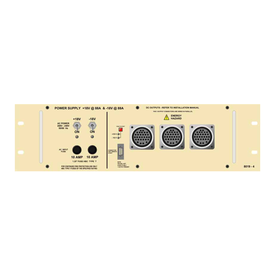
- Page 132 3) are soldered onto the motherboard adjacent to the 'input RFI filter' compo- nents. %1#6ZLWFK00RGH#3RZHU#6XSSO\#8QLWV CADAC 8019 and 8020 switch-mode power supply units were introduced during November 1998. The a.c. input supply has been ‘standardised’ at 208V to 240V 50/ 60Hz.
- Page 133 ;353#´469µ#VZLWFK0PRGH#SRZHU#VXSSO\#XQLW The 8020 +13v/48v unit is based on one ADVANCE F20006 ‘power-block’, with addi- tional circuitry as shown on CADAC drawing number C3.8016. The a.c. input is connected to the PSU via a 3-core cable, CMA reference 3183TQ – BASEC approved, rated at 20A.
- Page 134 (NOTE: DO NOT attempt to service the blocks. Lethal DC-voltages are exposed underneath the cover.) 15. If MAINS OK LED does not come on, check the fuse. The fuse should only be replaced with a 10A HBC TYPE T fuse. B-Type Revision B2005-2...
- Page 135 The CADAC consoles have a system of logging these unexpected events (and some of the user actions) in the battery backed memory of the Central Control Module.
- Page 136 Unrecognized destination in MIDI Block Message 0,',6HT#2YHUIORZ The input buffer has been completely filled while recording a MIDI sequence. The recording must stop. The following message can occur when using the older serial RS232 communica- tions: 7;#%XII#2YHUIORZ %DG#/RFDO#5HVHQG 1R#UHSO\#IURP#3& 7;#%XIIHU#)XOO %UHDN#UHFHLYHG B-Type Revision B2005-2...
- Page 137 1HZ#&ORFN=#Q0+] The CCM is able to work with older CADAC automaton software that requires serial RS232 communications. To do this, we have to change the crystal clock frequency of the micro-processor in the CCM. This is recorded in the Error Log with one of two...
- Page 138 7. Move the fader, ensuring operation is smooth. In most cases, the above cleaning and re-lubrication will improve the operating feel of a well-use fader. If it does not, then please consult Penny & Giles for further guid- ance. B-Type Revision B2005-2...
- Page 139 Enable options 2-15 Enable switches 2-15 Ethernet - BNC 1-14 Ethernet - RJ45 1-15 Event duration 2-18 Events 2-7 Fader communications 1-11, 2-7 Fader Mapping 2-11 Fast copper communications 1-16 Fast Copper Communications I/O 2-6 Frame rear connections 1-1 Revision B2005-2 B-Type...
- Page 140 MIDI All Notes Off 2-16 MIDI inputs and outputs 2-7 MIDI PC-filter 2-16 Module level software 2-8 Module power-up state 2-8 Motor fader behaviour when switching between modes 2-18 Motor Faders 2-4 Mouse 1-15 mouse 1-15 NOT ISOLATE mode 2-8 B-Type Revision B2005-2...
- Page 141 Stereo Input Module 7804 5-1 switch wiring 2-7 Switching ON 1-20 Switch-Mode Power Supply Units 1-3 System power-down procedure 1-20 System power-up 1-20 System power-up procedure 1-20 System Setup menu 2-10 System test 2-12 system voltage 1-5 Revision B2005-2 B-Type...
- Page 142 Using the “Remote-Start” function 1-7 Using the Video and Keyboard Change over function with Séance 1-18 VGA 1-16 Video and Keyboard Change over function 1-18 View Error Log 2-14 Wiring the switches 1-7 Write 2-5 XLR connections APP-II B-Type Revision B2005-2...
Need help?
Do you have a question about the B-Type and is the answer not in the manual?
Questions and answers