Table of Contents
Advertisement
Quick Links
WARNINGS:
• TO AVOID FIRE, SHOCK, OR DEATH; TURN OFF POWER AT CIRCUIT BREAKER
OR FUSE AND TEST THAT POWER IS OFF BEFORE WIRING!
• To be installed and/or used in accordance with appropriate electrical codes
and regulations.
• If you are unsure about any part of these instructions, consult an electrician.
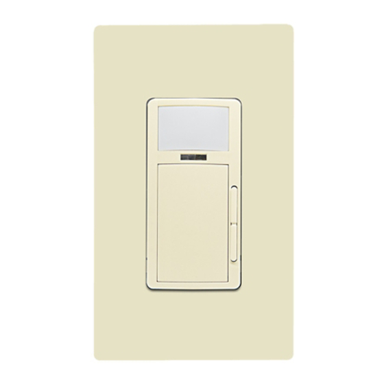
Product Description
Leviton Cat. No. ODP10-M1, Wall Switch and Dimming Occupancy Sensor, is designed to
easily switch and dim incandescent and dimmable LED or CFL bulbs while monitoring a
room for occupancy using Passive Infrared (PIR) and Microphonics detection technology.
The PIR uses a specialized segmented lens that divides the field of view into sensor
zones. When a person passes into or out of a sensor zone, the sensor detects motion
and switches the lights ON. The Microphonics technology will listen for human activity in
the space and will help keep lights ON while the space is occupied. Lighting levels can
be manually adjusted using the dimming bar next to the switch. The lights will remain
ON as long as there is an occupant moving through the sensor zones or while human
activity in the space can be heard.. ODP10-M1 can also be programmed to vacancy
mode (Manual ON/Auto OFF) for installations where Manual ON switching is required
for Title 24 applications. The ODP10-M1 provides a 180° field of view with a maximum
coverage area of approximately 1100 square feet. The maximum sensing distance in front
of the sensor is 30-40 feet, and 15-20 feet on either size. A "minor motion" zone detects
small body movements and allows the lights to stay ON even though a person may not
be moving or walking around the room. The remainder of the field of view, the "major
motion" zone, exhibits a lesser degree of sensitivity and requires larger movements.
Simple configuration can also be applied using push button setup for several popular
preconfigured options. ODP10-M1 is also equipped with a photocell for daylighting which
is programmable using the Leviton Smart Sensor App.
Before Installation
• Install into any single gang device wallbox.
• Supports multi-gang installations.
• Installation wire must be rated at least 90°C.
• Ivory, light almond, black, red, and gray faceplates are available with a color change kit
(sold separately).
• Decora
wallplate not included.
®
FOR OPTIMAL PERFORMANCE:
The ODP10-M1 sensor lens establishes dozens of zones of detection. The sensor is
sensitive to the heat emitted by the human body. In order to trigger the sensor, the PIR
must be triggered first. Once ON, either sensing technology will keep the lights ON. Both
PIR and Microphonic sensitivity can be adjusted to optimize detection ability based on
room size. The sensor will turn OFF after 45 min with no PIR detection. The device is
most effective in sensing motion across its field-of-view, and less effective sensing motion
towards or away from its field-of-view. Keep this in mind when selecting the installation
location. Note that occupancy sensors respond to rapid changes in temperature, so care
should be taken not to mount the device near a climate control source (i.e. radiators,
air exchanges, and air conditioners). Hot or cold drafts will look like body motion to the
device and will trigger it if the unit is mounted too close. It is recommended to mount the
Occupancy Sensor at least 6 feet away from a climate control source. In addition, it is also
recommended NOT to mount the Occupancy Sensor directly under a large light source.
Large wattage bulbs (greater than 100W incandescent) give off a lot of heat and switching
the bulb causes a temperature change that can be detected by the device. Mount the
Occupancy Sensor at least 6 feet away from large bulbs. If it necessary to mount the
device closer, lower the wattage of the bulb directly overhead.
Horizontal Beam Diagram
15-20 ft
4.6-6.1 m
10 ft
3 m
0
10 ft
3 m
15-20 ft
4.6-6.1 m
20 ft
6.1 m
Installation
WARNING: TO AVOID FIRE, SHOCK, OR DEATH; TURN OFF POWER at circuit breaker
or fuse and test that power is off before wiring!
1.
Strip wires 0.75 in and connect as per wiring diagram. Ensure wires are firmly attached
and there is no exposed copper.
Blue
Black
Dimming
Lighting
Load
White
2.
Gently place the wires and your device into the wall box and attach with
screws provided.
3.
If desired, change switch color. (Sold separately.)
4.
Restore power and test ON/OFF operation. Locator light should be ON when switch is
in the OFF state.
5.
Install Decora
wallplate (not included).
®
Smart Wallbox Multi-Technology Sensors:
INSTALLATION INSTRUCTIONS
Vertical Beam Diagram
40-48 in
1.02-1.23 m
20 ft
6.1 m
Major motion coverage
1100 ft^2 (102m^2)
Minor motion coverage
400 ft^2 (37.2m^2)
30-40 ft
9.1-12.2m
Hot (Black)
White
Line
120 VAC,
60Hz
Green
Ground
Neutral (White)
Phase Cut Dimming
Cat. No. ODP10-M1
CAUTION:
• For indoor applications only.
• To avoid damage to the product, DO NOT use disinfecting products, including foggers,
sprays or other types of atomized cleaning agents. DO NOT spray liquid onto the
product. To clean use a damp cloth with mild soap.
• SAVE THESE INSTRUCTIONS.
6.
ODP10-M1 is designed to work and be fully functional right out of the box, settings
can be adjusted using the Leviton Smart Sensor App or simple push
button programming.
7.
Using the Leviton Smart Sensor App or push button programming, you can now
configure the sensor to your preferred settings. (Leviton Smart Sensor App,
downloadable from Google Play™ or the Apple App Store
enabled Android™ or iOS Device). Operating mode, sensor sensitivity, and sensor
timeout can be quickly adjusted. For more advanced settings such as daylighting and
nightlight configuration, the Leviton Smart Sensor App will need to be used for setup
and adjustments.
8.
Additional Smart Wallbox Sensors can be added to the room for 3-way, 4-way, or
greater applications. The devices can be linked together to control the room in unison and
expand the FOV coverage. Forming a system is simple using Leviton's Push to Pair (P2P)
technology. A system of up to 5 devices can be built. To form the system:
a. Ensure all devices are powered up and can control their own load where necessary.
NOTE: Additional devices can also act as a remote and do not need to control a load.
b. Press the ON/OFF button of one of the devices for 15 seconds and release the
button when the LED blinks YELLOW.
NOTE: After 5 seconds, light behind PIR lens will blink BLUE and then alternate
between BLUE and RED before blinking YELLOW
c. The Network is created/opened successfully when the device blinks BLUE/YELLOW.
NOTE: wait to add additional device(s) until the initial device blinks BLUE/YELLOW; If
there is more than one device already in the network, all devices in network will blink
BLUE/YELLOW when the network is opened successfully.
d. Go to additional device(s) you want joined to the initial device, and press the ON/
OFF button until the LED blinks yellow.
NOTE: only one room should go through P2P process at a time to avoid accidently
adding device(s) from adjacent rooms.
e. Repeat as necessary for other devices (maximum of 5 devices).
f. The P2P process is complete when the LED on the newly added device(s) blinks
BLUE/YELLOW pattern and the load turns ON.
About Push to Pair (P2P):
- The P2P pairing process takes about 30 seconds to complete and the P2P enrollment
process times out after 2 minutes. If you are not successful the first time, try again.
- If ON/OFF button is not released while LED is blinking YELLOW (between 15-20
seconds), the LED will then start blinking RED (between 20-25 seconds). Release the
button and start over.
- Additional devices do NOT need to be on the same circuit, they will connect and operate
together remotely. Additional devices do not need to be tied to a load and can act as
a remote.
- For 3-way or more applications, the additional sensors can be used to expand zone
capacity; sensitivity can be configured for each device based on room size and targeted
FOV coverage.
- Additional devices can be added at any time—just repeat the process above to add
additional devices to your system.
- If a device needs to be removed from the system, reset Bluetooth following the
instructions under Configuration and Programming instructions.
- If unsuccessful pairing devices, try resetting the Bluetooth for each device; see Bluetooth
reset under Configuration and Programming instructions.
30-40 ft
9.1-12.2m
Microphonics
Motion Indicator Light
PIR Lens and Nightlight
Dimming Level
Programming:
can be performed
by pressing button
(per install instructions)
Operation
PUSH-BUTTON: ODP10-M1 has a push button switch that will toggle the lights ON
or OFF. When mode is set to Auto ON / Auto OFF, the lights will automatically turn ON
when occupancy is detected and will turn OFF automatically after occupancy is no
longer detected and the timeout has expired. If mode is set to Manual ON / Auto OFF,
the lights will only turn ON when the push button switch is pressed; the lights will turn
OFF automatically after occupancy is no longer detected and the timeout has expired.
If the lights are ON, the lights can be turned OFF when the button is pressed. The lights
will stay OFF (regardless of motion detected) until the timeout expires. After the timeout
expires, the lights will turn ON when the next motion is detected. This is useful for slide or
film presentations.
DIMMING BAR: The lights can manually be dimmed up or down by pressing the dimming
bar. To dim the lights down, press DOWN on the dimming bar and press UP to increase
the brightness.
NOTES:
• The Motion Indicator light will blink RED for 1 second each time motion is detected.
• In Manual ON mode, the button must be pressed to turn the lights ON. In the absence
of motion, the unit will time out and turn the lights OFF.
Indicator
DI-010-ODP10-02A-X1
ENGLISH
, using any Bluetooth™
®
Air Gap Switch
Photocell and
Locator Light
ON/OFF
Button
Dimming Bar
Advertisement
Table of Contents

Related Manuals for Leviton ODP10-M1


Summary of Contents for Leviton ODP10-M1
- Page 1 INSTALLATION INSTRUCTIONS Product Description ODP10-M1 is designed to work and be fully functional right out of the box, settings can be adjusted using the Leviton Smart Sensor App or simple push Leviton Cat. No. ODP10-M1, Wall Switch and Dimming Occupancy Sensor, is designed to button programming.
- Page 2 Trademark Disclaimer The Leviton logo and Decora are registered trademarks of Leviton Manufacturing Co., Inc. Google Play and Android are trademarks of Google, LLC. The Apple App Store is a registered trademark of Apple, Inc. Bluetooth is a trademark of Bluetooth SIG, Inc. Use herein of other third party trademarks, service marks, trade names, brand names and/or product names are for informational purposes only, are/may be the trademarks of their respective owners; such use is not meant to imply affiliation, sponsorship, or endorsement.
Need help?
Do you have a question about the ODP10-M1 and is the answer not in the manual?
Questions and answers