Table of Contents
Advertisement
Quick Links
WARNINGS AND CAUTIONS:
• TO AVOID FIRE, SHOCK, OR DEATH; TURN OFF POWER AT CIRCUIT BREAKER OR FUSE AND TEST THAT THE
POWER IS OFF BEFORE WIRING!
• DO NOT control a load in excess of the specified ratings. Damage to the unit, fire, electric shock, personal injury or
death can occur. Check your load ratings to determine suitability for your application.
• To be installed and/or used in accordance with electrical codes and regulations.
• If you are not sure about any part of these instructions, consult an electrician.
TOOLS NEEDED TO INSTALL YOUR SENSOR
Slotted/Phillips Screwdriver
Electrical Tape
Pliers
Cutters
Small Slotted Screwdriver
• CEC Title 20 and 24 Compliant
• Manual ON / Auto OFF
• Time Delay: 30 seconds to 30 minutes
• LED (Red): Visible status indicator for determining sensing technology operation
• Vacancy Confirmation: a 30 second grace period is enabled in case of False OFF
• Adjustable horizontal blinders for both left and right PIR masking.
• Leviton's Decora
®
style design
• Switches electronic ballasts
• Low Profile, tamper-resistant lens
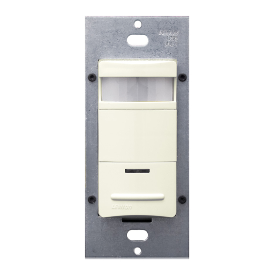
DESCRIPTION
Leviton Cat. No. ODS10-TD, Designer Wall Switch Vacancy Sensor, is designed to
detect motion from a heat-emitting source (such as a person in a room) within its
field-of-view (monitored space) and automatically switch lights OFF when no motion is
detected and the scheduled time-delay has expired.
Cat. No. ODS10-TD is UL and cUL listed.
The Vacancy Sensor senses motion within its coverage area of 2100 sq. ft (195.1 m
maximum and controls the connected lighting. This is a self-contained device which
provides sensing and light control. The Vacancy Sensor Manual ON feature will only
turn the lights ON when the user presses the switch, and keep the lights ON for as long
as motion is detected.
The Vacancy Sensor uses a small semiconductor heat detector that resides behind
a multi-zone optical lens. This Fresnel lens establishes dozens of zones of detection.
The sensor is sensitive to the heat emitted by the human body. In order to trigger
the sensor, the source of heat must move from one zone of detection to another.
The device is most effective in sensing motion across its field-of-view, and less
effective sensing motion towards or away from its field-of-view (refer to Field-of-View
diagrams). Keep this in mind when selecting the installation location (refer to Field-of-
View diagrams).
Note that vacancy sensors respond to rapid changes in temperature, so care should
be taken not to mount the device near a climate control source (i.e. radiators, air
exchanges, and air conditioners). Hot or cold drafts will look like body motion to the
device and will trigger it if the unit is mounted too close. It is recommended to mount
the Vacancy Sensor at least 6 ft. away from the climate control source. The device
can be mounted in a single gang wallbox.
In addition, it is also recommended NOT to mount the Vacancy Sensor directly under
a large light source. Large wattage bulbs (greater than 100W incandescent) give off a
lot of heat and switching the bulb causes a temperature change that can be detected
by the device. Mount the Vacancy Sensor at least 6 ft. away from large bulbs. If it
necessary to mount the device closer, lower the wattage of the bulb directly overhead.
Fluorescent - 1200VA - 10A @ 120V - Fluorescent - 2700VA - 10A @ 277V
Compatible with electronic and magnetic ballasts, electronic and magnetic low-voltage ballasts, incandescent lamps, and fans.
INSTALLING YOUR SENSOR
NOTE: Use check boxes
when Steps are completed.
WARNING:
TO AVOID FIRE, SHOCK, OR DEATH; TURN OFF POWER at
Step 1
circuit breaker or fuse and test that power is off before wiring!
OFF
ON
OFF
ON
OFF
ON
OFF
ON
OFF
ON
OFF
ON
OFF
ON
OFF
ON
OFF
ON
OFF
ON
OFF
ON
OFF
ON
Identifying your wiring application (most common):
Step 2
1
1
2
2
3
3
4
)
2
Single-Pole
3-Way
1. Line (Hot)
1. Line or Load (See important* instruction)
2. Ground
2. Ground
3. Load
3. First Traveler – note color
4. Second Traveler – note color
IMPORTANT: For 3-Way applications, note that one of the screw terminals from the old
switch being removed will usually be a different color (Black) or labeled Common. Tag
that wire with electrical tape and identify as the common (Line or Load) in both switch
wall boxes.
Preparing and connecting wires:
Step 3
(1.4 cm)
Cut
(if necessary)
• Pull off pre-cut insulation from sensor leads.
• Make sure that the ends of the wires from the wall box are straight (cut if necessary).
• Remove insulation from each wire in the wall box as shown.
Single Pole (One Location) or Multi-Location
Designer Wall Switch Vacancy Sensor
California Title 20 and 24 Compliant
Cat. No. ODS10-TD
Incandescent - 800W - 6.67A @ 120V
Supplemental - 1/4hp - 5.8A @ 120V
No Minimum Load Required
INSTALLATION INSTRUCTIONS
WARNINGS AND CAUTIONS:
• Do not install this unit to control a receptacle.
• Do not touch the surface of the lens. Clean outer surface with a damp cloth only.
• The Cat. No. ODS10-TD vacancy sensor is intended to replace a standard light switch.
• Use this device with COPPER OR COPPER CLAD WIRE ONLY.
Installing your Sensor – Single-Pole Application:
Step 4
NOTE: The Cat. No. ODS10-TD requires a ground wire to operate properly. If there is no
ground wire, ensure electrical box is grounded and attach ground wire to box with a screw.
If the ground wire is floating this device will not work.
Hot (Black)
Black
Line
120-277VAC
50/60 Hz
Neutral (White)
WIRING SENSOR:
Connect wires per WIRING DIAGRAM as follows: Screw wire connector on clockwise
making sure there are no bare conductors below the wire connectors. Secure each connector
with electrical tape.
• Green or bare copper wire in wall box to Green lead.
• Line Hot wall box wire to Black lead.
• Load wall box wire to Blue lead.
NOTE: Allow 1 minute for warm-up after connecting and energizing.
Strip Gage
9/16"
(measure bare
wire here)
Installing your Sensor – 3-Way Wiring Application:
Step 5
NOTE: The Cat. No. ODS10-TD requires a ground wire to operate properly. If there is
no ground wire, ensure electrical box is grounded and attach ground wire to box with a
screw. If the ground wire is floating this device will not work.
Sensor
Blue
Hot
(Black)
Black
Load
Line
Green
120-277VAC
Ground
White
50/60 Hz
Neutral (White)
NOTE: Either sensor can turn the lights ON. Both sensors must time out to OFF.
WIRING SENSOR 1:
Connect wires per WIRING DIAGRAM as follows:
• Green or bare copper wire in wall box to Sensor 1 Green lead.
• Line Hot (common) wall box wire identified (tagged) when removing old switch and First
traveler from Sensor 2 to Sensor 1 Black lead.
• Second Traveler wall box wire from Sensor 2 to Sensor 1 Blue lead.
WIRING SENSOR 2:
Connect wires per WIRING DIAGRAM as follows:
• Green or bare copper wire in wall box to Sensor 2 Green lead.
• Load wall box wire identified (tagged) when removing old switch and Second Traveler
from Sensor 1 to Sensor 2 Blue lead.
• First Traveler Line Hot from Sensor 1 to Sensor 2 Black lead.
NOTE: Allow 1 minute for warm-up after connecting and energizing.
DI-N0X-ODS10-00A
Sensor 2
Sensor 1
Blue
Blue
Black
Black
Black
Load
Green
Green
Ground
Ground
White
Advertisement
Table of Contents

Subscribe to Our Youtube Channel
Related Manuals for Leviton decora ODS10-TD Series


Summary of Contents for Leviton decora ODS10-TD Series
- Page 1 NOTE: Either sensor can turn the lights ON. Both sensors must time out to OFF. Connect wires per WIRING DIAGRAM as follows: Screw wire connector on clockwise Leviton Cat. No. ODS10-TD, Designer Wall Switch Vacancy Sensor, is designed to making sure there are no bare conductors below the wire connectors. Secure each connector...
- Page 2 Leviton Manufacturing Co., Inc., Att: Quality Assurance Department, 201 North Service Road, Melville, New York 11747. This warranty excludes and there is disclaimed liability for labor for removal of this product or reinstallation.
- Page 3 COMMENTS : The information in this document is the exclusive PROPRIETARY property of LEVITON MANUFACTURING COMPANY, INC. It is disclosed with the understanding that acceptance or review by the recipient constitues an undertaking by the recipient. (1) to hold this information in strict confidence, and (2) not to disclose, duplicate, copy, modify or use the information for any purpose other than that for which disclosed.
Need help?
Do you have a question about the decora ODS10-TD Series and is the answer not in the manual?
Questions and answers