Advertisement
Quick Links
WARNINGS AND CAUTIONS:
• TO AVOID FIRE, SHOCK, OR DEATH, TURN OFF POWER at circuit breaker or fuse, and test that power is off before wiring!
• DISCONNECT POWER AT CIRCUIT BREAKER OR FUSE WHEN SERVICING, INSTALLING, OR REMOVING FIXTURE.
• DO NOT control a load in excess of the specified ratings. Damage to the unit, fire, electric shock, personal injury, or death can occur.
Check your load ratings to determine suitability for your application.
• If you are unsure about any part of these instructions, consult an electrician.
• Do not install this unit to control a receptacle.
TOOLS NEEDED TO INSTALL YOUR SENSOR
Slotted/Phillips Screwdriver
Electrical Tape
Pliers
Cutters
Small Slotted Screwdriver
FEATURES
• Leviton's Decora
®
style design.
• Sensor can be ganged together with other units in a multiple-switch
wall plate.
• Self-Adaptive Technology adjusts to occupancy patterns of use in
Auto-Adapt mode.
• The Adapting Time-Out Walk-Through feature prevents lights
from remaining ON for an extended period, after only a
momentary occupancy.
• Switches a single-load circuit.
• One push-button, which provides manual ON/OFF switching at
any time.
• Adjustable horizontal field-of-view.
• Integrated photocell prevents lights from turning ON when room is
adequately illuminated by natural light.
• True Zero-Cross relay provides maximum contact life and
compatibility with electronic ballasts.
• Dual-detection technology, both Passive Infrared and Ultrasonic.
Can be configured as Ultrasonic-Only, by disabling Passive Infrared.
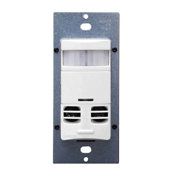
DESCRIPTION
Leviton's Designer Multi-Technology Wall Switch Occupancy Sensor,
Cat. No. OSSMT, is designed to detect motion, using the passive
infrared (PIR) sensor from sources (such as a person entering a
room) within its field-of-view (monitored space) to automatically
switch lights ON. The Occupancy Sensor senses motion within its
maximum coverage area of 2400 sq. ft (223 m
2
). The ultrasonic (US)
sensors work with the PIR to keep the lights ON when occupied. The
controlled lights will remain ON until no motion is detected, and the
scheduled Time-Delay has expired, at which point the lights will be
turned OFF. In Adapting Time-Out mode, the sensor adapts its
Time-Delay settings to the occupancy patterns of a room.
The OSSMT is an Occupancy Sensor that is designed to control a
single lighting control circuit and provide the energy savings of an
occupancy sensor.
The OSSMT is a single relay device, which can be Auto-ON or
Manual-ON. The device contains a photocell that provides an Ambient
Light Hold-Off function. The device is configurable for either Ultrasonic
with PIR, or Ultrasonic-Only modes of operation.
Cat. No. OSSMT-M3 is cETL listed and conforms to California
Title 24 requirements.
The PIR Occupancy Sensor uses a small semi-conductor heat
detector that resides behind a multi-zone optical lens. This Fresnel lens
establishes dozens of zones of detection. The Sensor is sensitive to the
heat emitted by the human body. In order to initially trigger the Sensor,
the source of heat must move from one zone of detection to another.
The device is most effective in sensing motion across its field-of-view,
and it is less effective at sensing motion towards or away from its field-
of-view. Keep this in mind when selecting the installation location (refer
to Field-of-View diagrams).
Multi-Technology Designer Wall Switch Occupancy Sensor
Operating Temperature Range: 32°F to 104°F (0°C to 40°C)
The US Occupancy Sensor uses a non-audible high-frequency (40kHz)
to sense Doppler shifts caused by motion in the space. The US is more
sensitive to small motion and does not rely on line-of-sight for detection.
If both sensors have not detected any motion for the set Time-Out period,
the relay and its corresponding load will be turned OFF.
Note that occupancy sensors respond to rapid changes in temperature,
so care should be taken NOT to mount the device near a climate control
source (e.g., radiators, air exchanges, and air conditioners). Hot or cold
drafts will look like body motion to the device and will trigger it if the unit
is mounted too close. It is recommended to mount the Occupancy
Sensor at least 6 feet away from a climate control source.
In addition, it is also recommended NOT to mount the Occupancy Sensor
directly under a large light source. Large wattage bulbs (greater than
100W incandescent) give off a lot of heat, and switching the bulb causes
a temperature change that can be detected by the device. Mount the
Occupancy Sensor at least 6 ft. away from large bulbs. If it is necessary
to mount the device closer, lower the wattage of the bulb
directly overhead.
INSTALLING YOUR SENSOR
NOTE: Use check boxes
when steps are completed.
WARNING:
TO AVOID FIRE, SHOCK, OR DEATH, TURN
Step 1
OFF POWER at circuit breaker or fuse, and test that power
is off before wiring!
Identifying Your Wiring Application
Step 2
(most common):
1
2
2
1
3
3
4
4
5
Single-Pole
Multi-location
1. Line (Hot)
1. Line or Load (See important*
2. Neutral
instruction)
3. Ground
2. Neutral
4. Load
3. Ground
4. First Traveler – note color
5. Second Traveler – note color
Note: This product is not true 3-way devices.
IMPORTANT: For Multi-location applications, note that one of the screw
terminals from the old switch being removed will usually be a different
color (Black) or labeled Common. Tag that wire with electrical tape and
identify as the Common (Line or Load) in both switch wall boxes.
Single-Pole (One Location) or Multi-Location
California Title 24 2005 Compliant
Cat. No. OSSMT-M3
Ballast: 1500VA @ 347V
Relative Humidity: 20% to 90% non-condensing
Minimum Load Not Required
INSTALLATION INSTRUCTIONS
WARNINGS AND CAUTIONS:
• To be installed and/or used in accordance with electrical codes and regulations.
• Mounts in standard 347V type box.
• The OSSMT Occupancy Sensor is intended to replace a standard single-pole Decora wall switch.
• Do not touch the surface of the lens. Clean outer surface with a damp cloth only.
• Use this device WITH COPPER OR COPPER-CLAD WIRE ONLY.
Preparing and Connecting Wires:
Step 3
Strip Gage
9/16"
(measure bare
(1.4 cm)
wire here)
Cut
(if necessary)
• Pull off pre-cut insulation from sensor leads.
• Make sure that the ends of the wires from the wall box are straight
(cut if necessary).
• Remove insulation from each wire in the wall box as shown.
Installing Your Sensor – Single-Pole Application:
Step 4
NOTE: Cat. No. OSSMT-M3 requires a Neutral wire. If there is no
Neutral wire, this device will not work.
OSSMT-M3
Blue
Black
Black (Hot)
Black
White
Load
Line
347VAC, 60Hz
Green
Ground
White
Neutral (White)
WIRING SENSOR:
Connect wires per WIRING DIAGRAM, as follows: Screw wire connector
on clockwise, making sure there are no bare conductors below the wire
connectors. Secure each connector with electrical tape.
• Green or bare copper wire in wall box to Green lead.
• Line Hot wall box wire to Black lead.
• Load wall box wire to Blue lead.
NOTE: Allow 1 minute for warm-up, after connecting and energizing.
Installing Your Sensor – Multi-location
Step 5
Wiring Application:
OSSMT-M3
Sensor 1
Sensor 2
Black (Hot)
Black
Blue
Blue
Black
Black
White
White
Line
347VAC, 60Hz
Load
Green
Green
White
Ground
Ground
Neutral (White)
NOTE: Sensor 1 must be installed in a wall box that has both a LINE Hot
and a Ground connection. Sensor 2 must be installed in a wall box that
has both a Load and a Ground connection.
If you are unsure about any part of these instructions, consult
an electrician.
NOTE: Either sensor can turn the lights ON. Both sensors must
Time-Out to OFF, or both manual buttons must be pressed for the lights
to go OFF.
WIRING SENSOR 1:
Connect wires per WIRING DIAGRAM, as follows:
• Green or bare copper wire in wall box to Sensor 1 Green lead.
• Line Hot (common) wall box wire, identified (tagged) when removing old
switch, and First traveler from Sensor 2 to Sensor 1 Black lead.
• Second Traveler wall box wire from Sensor 2 to Sensor 1 Blue lead.
• Tie Neutral wires together.
WIRING SENSOR 2:
Connect wires per WIRING DIAGRAM, as follows:
• Green or bare copper wire in wall box to Sensor 2 Green lead.
• Load wall box wire, identified (tagged) when removing old switch, and
Second Traveler from Sensor 1 to Sensor 2 Blue lead.
• First Traveler Line Hot from Sensor 1 to Sensor 2 Black lead.
NOTE: Allow 1 minute for warm-up, after connecting and energizing.
DI-71X-OSSMT-02B
Testing Your Sensor Prior to Completely
Step 6
Mounting in Wall Box:
Wall surface
Mounting
screws
(2 places)
Sensor
NOTE: Dress wires with a bend, as shown in diagram, to relieve stress
when mounting device.
• Position all wires to provide room in outlet wall box for device.
• Partially secure device, using long mounting screws provided.
• Restore power at circuit breaker or fuse.
NOTE: Allow 1 minute for warm-up, after energizing.
NOTE: All models of the OSSMT are factory preset to work without
any adjustments. If necessary, adjust the Blinders and PIR Range
Control to stop any unwanted activation of the lights (refer to
FEATURES section).
• For additional Time Control settings, refer to the SETTINGS section.
NOTE: To avoid PERMANENT DAMAGE to the unit, be careful
NOT TO OVERTURN the control knobs or levers when setting the
Sensor. The controls can be accessed by removing the wall plate
(if applicable) and Control Panel cover (refer to Control Panel
Diagram). Use a small straight-blade screwdriver to adjust knobs
and Blinder levers.
NOTE: DO NOT press in on blinder levers or use excessive force
(refer to Control Panel Diagram).
• Attach the Control Panel cover when the desired settings
are complete.
If lights do not turn ON, refer to the TROUBLESHOOTING section.
FEATURES
NOTE: To access Control settings, remove the Control Panel cover.
Factory Settings: The sensor is shipped from the factory to work in
almost all situations, without any added adjustments. The factory settings
are: Blinders open, 10 minutes fixed Time-Out, Lights always turn ON
regardless of existing light levels, Medium Passive Infrared (PIR) range,
and Medium Ultrasonic range. The PIR and Ultrasonic technologies are
both active.
Blinders: The Blinders are two independent shutters that can narrow the
field-of-view from a maximum of 180°, down to medium. The Blinders are
operated by moving the Blinder levers towards or away from the center
of the Sensor. The Blinder levers can be found above the control dials in
the Control Panel (refer to Control Panel Diagram).
Time-Outs: The Sensor has three types of Time-Outs: Fixed, Adapting,
and Walk-Through.
• Fixed Time-Out: The value of this Time-Out is user-selected,
through the use of the Time Control setting (refer to Control Panel
Diagram and Time-Out settings).
• Adapting Time-Out: When activated, the value of this Time-Out
(30 minutes) is changed by the Sensor, based on room occupancy
and lighting conditions.
• Walk-Through Time-Out: The value of this Time-Out is preset to
2.5 minutes, and only exists in the Adapting Time-Out mode.
Advertisement

Related Manuals for Leviton decora OSSMT-M3


Summary of Contents for Leviton decora OSSMT-M3
- Page 1 First traveler from Sensor 2 to Sensor 1 Black lead. Line NOTE: DO NOT press in on blinder levers or use excessive force Leviton's Designer Multi-Technology Wall Switch Occupancy Sensor, • Second Traveler wall box wire from Sensor 2 to Sensor 1 Blue lead. 347VAC, 60Hz (refer to Control Panel Diagram).
- Page 2 Leviton is not liable for incidental, indirect, special, or consequential damages, including without limitation, damage to, or loss of use of, any equipment, lost sales or profits or delay or failure to perform this warranty obligation.
Need help?
Do you have a question about the decora OSSMT-M3 and is the answer not in the manual?
Questions and answers