Table of Contents
Advertisement
Quick Links
Features
FM & LoRa Spread Spectrum
•
FM up to 1Km line of sight
•
LORA up to 20Km line of sight
•
2 x Closed Contact Inputs
•
2 x Relay Switch Outputs
•
Add-on Input/ Output channels
•
Expandable to 16 I/P's / 32 O/P's
•
All Signals 'Acknowledged'
•
Independent Watchdog Feature
•
Walk / Range test Mode
•
12-32V ac or dc Supply
•
LED Bar graph Signal indicator
•
Mom, Latched or Timed Outputs
•
Antenna Supplied
•
Easy Installation
•
868MHz Version CE compliant
•
918MHz FCC pending
•
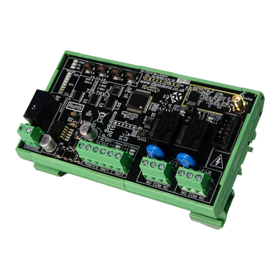
The 725TRX telemetry system provides, transceiver, remote Telemetry System. Each module
has two switch inputs and two relay changeover contact outputs. When two or more modules
are paired together the relay outputs will follow the state changes of the other modules' in-
puts. The 725TRX can also be used with any RF Solutions Transmitter Handset operating on
the same frequency
Additional input / output modules can be connected to provide extra inputs/outputs. The system
inputs / outputs can be used in various ways and also with a hand held keyfob or alternative
handset.
All signals are acknowledged and a watchdog feature provides a system "Alive" indication. This
is automatic, allowing the user to simply connect to the screw terminals and achieve a reliable
telemetry link.
20Km LoRa Radio Telemetry Modules
Intended Use
Industrial Telemetry
•
Remote Monitoring & Control
•
Reliable Remote Switch
•
DS-725-5
725 Series
Advertisement
Table of Contents

Related Manuals for RF SOLUTIONS 725 Series


Summary of Contents for RF SOLUTIONS 725 Series
- Page 1 When two or more modules are paired together the relay outputs will follow the state changes of the other modules’ in- puts. The 725TRX can also be used with any RF Solutions Transmitter Handset operating on the same frequency Additional input / output modules can be connected to provide extra inputs/outputs.
-
Page 2: Safety Information
Safety Information Carefully read the following safety information before proceeding with installation, operation, or maintenance of RF Solutions product. Failure to follow these warnings could result in death or serious Injury • This radio system must not be used in areas where there is a risk of explosion. -
Page 3: Information Sur La Sécurité
725 Series Information sur la sécurité Lisez attentivement les informations de sécurité suivantes avant de procéder à l'installation, l'utilisation ou la maintenance du produit RF Solutions. Le non-respect de ces avertissements peut entraîner la mort ou des blessures graves •... - Page 4 725 Series Veiligheidsinformatie Lees de volgende veiligheidsinformatie zorgvuldig door voordat u doorgaat met de installatie, bediening of het onderhoud van het RF Solutions-product. Het niet opvolgen van deze waarschuwingen kan de dood of ernstig letsel tot gevolg hebben • Dit radiosysteem mag niet worden gebruikt in gebieden waar explosiegevaar bestaat.
-
Page 5: Elektrische Sicherheit
Sicherheitsinformation Lesen Sie die folgenden Sicherheitsinformationen sorgfältig durch, bevor Sie mit der Installation, dem Betrieb oder der Wartung des RF Solutions-Produkts fortfahren. Die Nichtbeachtung dieser Warnungen kann zum Tod oder zu schweren Verletzungen führen. • Dieses Funksystem darf nicht in explosionsgefährdeten Bereichen eingesetzt werden. -
Page 6: Información De Seguridad
725 Series Información de seguridad Lea atentamente la siguiente información de seguridad antes de continuar con la instalación, operación o mantenimiento del producto de RF Solutions. El incumplimiento de estas advertencias podría provocar la muerte o lesiones graves. • Este sistema de radio no debe utilizarse en áreas donde exista riesgo de explosión. -
Page 7: Informazioni Sulla Sicurezza
725 Series Informazioni sulla sicurezza Leggere attentamente le seguenti informazioni sulla sicurezza prima di procedere con l'installazione, il funzionamento o la manutenzione del prodotto RF Solutions. La mancata osservanza di queste avvertenze può provocare morte o lesioni gravi • Questo sistema radio non deve essere utilizzato in aree a rischio di esplosione. -
Page 8: Products Overview
725 Series Products Overview 725TRX Transceiver • Self Contained Telemetry Transceiver • 2 No volt inputs • 2 Relay Outputs • 1 Watchdog Relay output • Supply Voltage 12-32V ac/dc • Supplied with antenna Part Number Description Range* 725-TRX8-FM 868MHz Transceiver FM only... - Page 9 725 Series 725TRX Overview WatchDog Press to initiate Watchdog Transmissions (also used for range test) Timer Sets ouput timers Mode see Timer settings for Select power output and Operating Mode. more details Pair Press once to auto sync. See Advanced operation for other pairing and erase options.
- Page 10 725 Series Creating a Telemetry System using Two 725 TRX’s Power Timer WatchDog Mode Pair Timer WatchDog Mode Pair Power Strength Strength 100% 100% WATCHDOG NO COM NC NO COM NC WATCHDOG NO COM NC NO COM NC Follow these Steps: Connect to screw Terminal Inputs.
- Page 11 725 Series Pairing a hand held transmitter To AUTO-PAIR a hand held transmitter: Press and release the PAIR button on the 725TRX. The pair and all relay output LED’s will flash on 725TRX.* Activate ANY button on your transmitter. All flashing LEDs on 725TRX relays will go out. The PAIR LED will flash quickly for 2 seconds .
- Page 12 725 Series INPUTs Status LEDs Inputs are activated by a closed contact ‘no volt’ switch. When the status of any input is changed 725TRX immediately broadcasts the status (of all inputs). After receiving the transmitted RF signal, the paired 725TRX Transceiver(s) respond with an ACKNOWLEDGE RF Signal.
- Page 13 725 Series MOMENTARY/LATCHING setting links Each Relay Output can be individually pre-set to Momentary/Latching by fitting or removing the Link Headers Timer WatchDog Mode Pair Power Strength 100% WATCHDOG NO COM NC NO COM NC Link fitted LATCHING Output changes state on each Transmit signal...
- Page 14 725 Series RF Mode of Operation The 725TRX LORA modules can be configured to operate as standard FM or LoRA Modes.1-7 = (FSK) fixed frequency Carrier Frequency (provides a fast Time of operation over a shorter range) LoRA = Long Range Spread Spectrum Frequency Hopping Protocol (provide a longer range)
- Page 15 725 Series Watchdog This feature provides a System “Alive” failsafe function between Two 725TRX modules. When Watchdog is enabled a 725TRX automatically transmits a background Radio signal at the preset time interval. Any paired 725TRX receiving an RF packet from another paired 725TRX will activate its “Watchdog re- lay output”.
- Page 16 725 Series Additional Input / Output Modules Up to 4 Input and 4 Output modules can be added (16 inputs and 16 outputs (725- OP) 32 outputs (725-DOP8) max). Cables are supplied to enable the modules to plug and play.
- Page 17 725 Series 725-DOP8 Additional Outputs Module Digital outputs Outputs OUTPUT OUTPUT OUTPUT OUTPUT Power Connect to Connect to Further Further Add on Add on Modules Modules Address OUTPUT OUTPUT OUTPUT OUTPUT Power In Digital outputs Outputs The 725-DOP8 module provides 8 Switching Outputs.
- Page 18 725 Series Connecting Add-on Input / Output Modules Address settings: Each module must have a unique address set by the Address jumpers (it doesn't matter what the address is) Note: When pairing outputs will cycle in address order . Connect to 725TRX:...
- Page 19 725 Series Application Example using Multiple Add-on Modules In this Below example; ‘A’ inputs are paired directly with ‘B’ Outputs ‘B’ inputs are paired directly with ‘A’ Outputs Power Timer WatchDog Mode Pair Power Address Power Address Address Power Power...
- Page 20 725 Series More Advanced Example - using Multiple Transceiver Modules Application Example: In the example below ‘A’ input 1 is paired with ‘B’ Output2 ‘A’ input 2 is paired with ‘C’ output 1 ‘B’ input 2 is paired with ‘C’ output 2 Note: Do not pair more than one output relay with each input.
- Page 21 725 Series Optional Component Parts / Spares ENC-DA3 enclosure: • IP65 rated DIN rail enclosure • 12V volt PSU • 305mm X 220mm X 125mm • Premade Back plate with DIN Rail Mount • Easy clip fit for 700 series products 12V1A-IN-IP: •...
- Page 22 725 Series Technical Specifications Transceiver: 725-TRX Dimensions: 136 x 78 x 42 mm Storage Temperature: -10 to +70 Celsius. Operating Temperature: -10 to +50 Celsius Electrical Characteristics Typical Units Note Vdc or Supply Voltage 869.500 Frequency: 918.000 RF Output Power (ERP)
- Page 23 725 Series Product Identification and Revision Control Product Ident label is mounted On the Rear of the module Revision Change History Part Change / Fix Revision 725-TRX8-1K Bug Fix to fix Momentary Mode 725-TRX8-16K 725-TRX8-1K 725-TRX8-16K 725-TRX9-1K Update to Firmware to make 725-IP functionally compatible with other RF...
- Page 24 Text der EU-Konformitätserklärung ist unter der folgenden Internetadresse verfügbar: www.rfsolutions.co.uk EL - Με την παρούσα ο/η RF Solutions Limited , δηλώνει ότι ο ραδιοεξοπλισμός ορίζεται σε αυτό το έγγραφο πληροί την οδηγία 2014/53/ΕΕ. Το πλήρες κείμενο της δήλωσης συμμόρφωσης ΕΕ διατίθεται στην ακόλουθη ιστοσελίδα στο διαδίκτυο: www.rfsolutions.co.uk...
Need help?
Do you have a question about the 725 Series and is the answer not in the manual?
Questions and answers