Table of Contents
Advertisement
Quick Links
Features
Small Form Factor
2 Analogue I/O (10bit)
Data Reception LED
Secure Data Protocol
Easy Pairing Process
One to One operation
M100mW Transmit Power
10 Digital Input / Outputs
Range up to 2,000 Metres
Minial external components
868MHz Operating Frequency
10 Channel Transceiver Module
CE Compliant, Licence Free Use
Ultra Low Voltage 2.2—3.6V
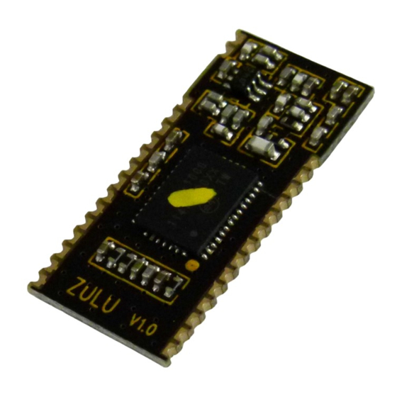
The ZULU-T Telemetry Module provides a reliable Transceiver based
industrial Remote Switch with up to 2,000 metres range. Two
modules are combined to provide a simple network of radio switch-
ing.
Each unit is supplied ready to operate, once paired with another
Module a remote control system is created
Connections for Power, antenna and Input / Output are the only
connections required
DS-ZULUT-6
Arrow.com.
Downloaded from
Smart Radio Telemetry Module
Part No
ZULU-T868
ZULU-T868-SO
Description
Radio Telemetry Module DIP Package
Radio Telemetry Module SMT Package
ZULU T
Applications
Remote Control
Remote Networking
Remote Switching
Remote Traffic Lights
Advertisement
Table of Contents

Subscribe to Our Youtube Channel
Related Manuals for RF SOLUTIONS ZULU-T868


Summary of Contents for RF SOLUTIONS ZULU-T868
- Page 1 Each unit is supplied ready to operate, once paired with another Module a remote control system is created Connections for Power, antenna and Input / Output are the only connections required Description Part No ZULU-T868 Radio Telemetry Module DIP Package ZULU-T868-SO Radio Telemetry Module SMT Package DS-ZULUT-6 Arrow.com.
- Page 2 ZULU Telemetry Pin out Zulu An / Dig XTAL 1 I/O 1 XTAL 2 I/O 2 IRQ_OUT I/O 3 I/O 10 I/O 9 I/O 4 I/O 8 I/O 5 IRQ_IN I/O 6 I/O 7 WD_SEL CH_SEL ERR_LED TX_RX_SEL RF_TX_LED RF_RX_LED Pin Description Pin No Name...
- Page 3 ZULU Telemetry General Description of Operation Each module can be set to act as a ‘ Transmitter’ or ‘Receiver’ A remote telemetry system is achieved when two modules are paired together, as transmitter (ZuluTx) and receiver (ZuluRx). Each time an input changes on the ZuluTx, it will transmit the status of its inputs to the paired ZuluRx(s).
- Page 4 ZULU Telemetry The following descriptions apply to the Zulu Module in TRANSMITTER Mode When configured as a Transmitter the ZULU Module will automatically default to low power sleep mode until any input state change takes place. On receipt of an input state change the ZuluTx will transmit a packet showing the status of all inputs (multiple state changes can take place simultaneously).
- Page 5 ZULU Telemetry Transmitter example application circuit XTAL Analogue Inputs ZULU-T RF Fault TX LED Notes: Watchdog is ON RX LED Channel selected is 869.500 Analogue inputs active SWITCH INPUTS 8 - 10 SWITCH INPUTS 3 - 7 DS-ZULUT-6 Arrow.com. Arrow.com. Arrow.com.
-
Page 6: Analogue Output
ZULU Telemetry The following descriptions apply to the Zulu module in RECEIVER mode Analogue outputs (pin 4, 5) If enabled the ZuluRx outputs PWM signal. The PWM may be used directly (e.g. for motor control) The PWM signal is a proportional digital output representing the analogue input. If the analogue input is 0V then the PWM output will be ‘0’... - Page 7 ZULU Telemetry Receiver Application Circuit XTAL Analogue Outputs ZULU-T LEARN RF Fault TX LED RX LED LED OUTPUTS 3 - 7 LED OUTPUTS 8 - 10 Notes: Watchdog is ON Channel Selected is 869.500 Analogue outputs active DS-ZULUT-6 Arrow.com. Arrow.com. Arrow.com.
- Page 8 ZULU Telemetry Application Example ONE to ONE Input 1 - 10 Zulu Zulu Transmit Signal Output 1 - 10 Transmitter Receiver Acknowledge In this application the outputs at the receiver will track the inputs at the transmitter. The receiver outputs are acknowledged back to the transmitter. If required the Watchdog can be enabled to inform the user if the RF system has a fault.
-
Page 9: Mechanical Dimensions
ZULU Telemetry Mechanical Dimensions ZULU Notes 1. Pins 1.27mm pitch 2. Pin Dims 0.4mm sq 3. All dims in mm Range The antenna choice and position directly controls the system range. Keep it clear of other metal in the system. The best position by far, is protruding vertically from the top of the prod- uct. - Page 10 ZULU Telemetry Technical Specifications Absolute Maximums Temperature Range: Storage –50 to +125 Parameter Units Supply Voltage Voltage on any Input VDD >2.2V VDD <2.2V VDD + Max Input power (thro Antenna) Parameter Typical Units Supply Voltage Operating Temperature Zulu Tx Supply Current: When Transmitting When sleeping Zulu Rx Supply Current:...
-
Page 11: System Characteristics
ZULU Telemetry System Characteristics Parameter Typical Units Time from Zulu Tx input activation time to Zulu RX out- put Activation Time from Zulu Tx input activation time to Zulu RX out- put Relaxing DS-ZULUT-6 Arrow.com. Arrow.com. Arrow.com. Arrow.com. Arrow.com. Arrow.com. Arrow.com. - Page 12 ZULU Telemetry ZuluT Evaluation Board The ZULU EVAL Boards provide a ready to go platform which can be used for evaluation or complete projects. These boards demonstrate the capabilities of ZULU Modules.. Features Provides a Radio Link with; 10 Digital Channels ...
-
Page 13: Jumper Links
ZULU Telemetry ZuluT Evaluation Board Configuration Antenna Antenna Status LED’s Analogue Outputs Analogue ZULU RS232 Comms ZULU RS232 Comms (PWM) Inputs Module (not fitted as Module (not fitted as standard) standard) Comms Selector Link Comms Selector Link All centre to RS232, or All centre to RS232, or All Centre to USB All Centre to USB... -
Page 14: Pairing Process
ZULU Telemetry Pairing Process In order to pair together a Transmitter and receiver, On the Receiver Briefly press the Receiver ‘Sync Button’ Briefly operate any of the transmitter buttons For all other operation please refer to the ZULU Module operation Analogue in / PWM Out When using the analogue RF link, by turning the potentiometer VR1 or VR2, outputs 1 and 2 at the receiver will vary between 0 and 100% PWM, the EVAL-T board has these outputs con-... - Page 15 ZULU Telemetry Zulu evaluation board receiver schematic DS-ZULUT-6 Arrow.com. Arrow.com. Arrow.com. Arrow.com. Arrow.com. Arrow.com. Arrow.com. Arrow.com. Arrow.com. Arrow.com. Arrow.com. Arrow.com. Arrow.com. Arrow.com. Arrow.com. Downloaded from Downloaded from Downloaded from Downloaded from Downloaded from Downloaded from Downloaded from Downloaded from Downloaded from Downloaded from Downloaded from Downloaded from...
- Page 16 ZULU Telemetry Zulu evaluation board transmitter PCB layout DS-ZULUT-6 Arrow.com. Arrow.com. Arrow.com. Arrow.com. Arrow.com. Arrow.com. Arrow.com. Arrow.com. Arrow.com. Arrow.com. Arrow.com. Arrow.com. Arrow.com. Arrow.com. Arrow.com. Arrow.com. Downloaded from Downloaded from Downloaded from Downloaded from Downloaded from Downloaded from Downloaded from Downloaded from Downloaded from Downloaded from Downloaded from...
- Page 17 01273 898 000 Whilst the information in this document is believed to be correct at the time of issue, RF Solutions Ltd does not accept any liability whatsoever for its accuracy, adequacy or completeness. No express or implied warranty or representation is given relating to the information contained in this document. RF Solutions Ltd reserves the right to make changes and improvements to the product(s) described herein without notice.
Need help?
Do you have a question about the ZULU-T868 and is the answer not in the manual?
Questions and answers