Advertisement
Quick Links
Features
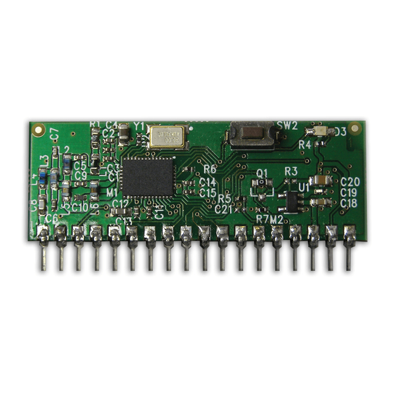
8 Channel transceiver module
•
Range up to 1,000 metres
•
8 Digital input/outputs
•
Receiver outputs mirror
•
transmitter inputs
Minimal external components
•
Secure data protocol
•
Ultra low power 1.8—3.6V
•
Easy pairing process
•
One to one and one to many operation
•
869.5 / 915MHz* operating versions
•
+13dBm transmit power
•
Single in line module
•
Incorporates Self Test Mode
•
CE compliant for licence free use
•
FCC Approved for use in USA (TBC)*
•
Description
The BRAVO-T telemetry module provides a reliable transceiver based industrial
remote switch with up to 1,000 metres range. Two or more modules may be
combined to provide a simple or complex network of radio switches.
Ordering Information
Part No
BRAVO-T868
BRAVO-T915 (TBC)*
SmartRadio Telemetry Module
Radio telemetry module SIL package 868MHz
Radio telemetry module SIL package 915MHz (TBC)*
DS-BRAVO-9
Applications
Remote Control
•
Remote Networking
•
Remote Switching
•
Remote Traffic Lights
•
Description
BRAVO
Advertisement

Subscribe to Our Youtube Channel
Summary of Contents for RF SOLUTIONS BRAVO-T868
- Page 1 1,000 metres range. Two or more modules may be combined to provide a simple or complex network of radio switches. Ordering Information Description Part No BRAVO-T868 Radio telemetry module SIL package 868MHz BRAVO-T915 (TBC)* Radio telemetry module SIL package 915MHz (TBC)* DS-BRAVO-9...
-
Page 2: Pin Description
BRAVO Telemetry Module Pin-out Bravo Learn Switch 10 11 12 13 14 15 16 17 18 Pin Description Pin No Name Direction Description Antenna input/output 50ohm impedance 2, 15 Connect to ground When configured as transmitter:Active low 3, 4, 7, 8, Digital inputs: high impedance inputs 9, 11, 12 I/O1-8... - Page 3 BRAVO Telemetry Module BRAVO Configured as a TRANSMITTER Operation When configured as a transmitter the BRAVO module will automatically default to low power sleep mode until any input state change takes place. On receipt of an input state change the BRAVO-Tx will transmit a packet showing the state of changed input/s (multiple input changes may take place simultaneously) Watchdog If watchdog is enabled the Bravo-Tx will transmit a background packet containing the current...
- Page 4 BRAVO Telemetry Module BRAVO Configured as a RECEIVER Watchdog enabled If “watchdog” is enabled the BRAVO-Rx will await a signal from a paired BRAVO-Tx module. When the Watchdog signal is received OK then the watchdog output will be main- tained active high. If no watchdog signal is received in any 30minute period then the BRAVO- Rx will drop the Watchdog output.
- Page 5 BRAVO Telemetry Module Pairing Process Bravo-Tx to Bravo-RX Each BRAVO module has a unique serial number identity. They may be paired together using the LEARN button/input so that they operate in systems in: one:one, one:many and many:one formats. Each BRAVO-Rx can store 70 BRAVO-Tx identities. Note: “watchdog”...
- Page 6 BRAVO Telemetry Module Operational application examples Application example one:one operation Input 1 - 8 Bravo Transmit Signal Bravo Output 1 - 8 Transmitter Receiver In this application the outputs at the receiver will match the inputs at the transmitter. one:many Application example: operation Bravo...
- Page 7 BRAVO Telemetry Module Mechanical Dimensions 40.5mm 34.5mm 48mm 10 11 12 13 14 15 16 17 18 2.33mm 2.54mm Notes 1. Pins 2.54mm pitch 2. Pin Dims 0.4mm sq 3. All dims in mm Range Considerations The antenna choice and position directly affects the system range, keep it clear of any large metal parts.
- Page 8 BRAVO Telemetry Module Technical Specifications Absolute Maximums: Temperature Range: Storage –50 to +125 DC Characteristics Parameter Units Supply Voltage -0.3 Voltage on any Input Vcc > 2.2V Vcc < 2.2V Vcc+3.6 Max Input power (through RX antenna) Max Current Sourced / Sunk (Per I/O) Max Current Sourced / Sunk (Total) DC Characteristics Parameter...
- Page 9 WEE/JB0104WV Whilst the information in this document is believed to be correct at the time of issue, RF Solutions Ltd does not accept any liability whatsoever for its accuracy, adequacy or completeness. No express or implied warranty or representation is given relating to the information contained in this document. RF Solutions Ltd reserves the right to make changes and improvements to the product(s) described herein without notice.


Need help?
Do you have a question about the BRAVO-T868 and is the answer not in the manual?
Questions and answers