Table of Contents
Advertisement
Quick Links
Advertisement
Table of Contents

Related Manuals for EarthQuaker Devices The Wave Transformer


Summary of Contents for EarthQuaker Devices The Wave Transformer
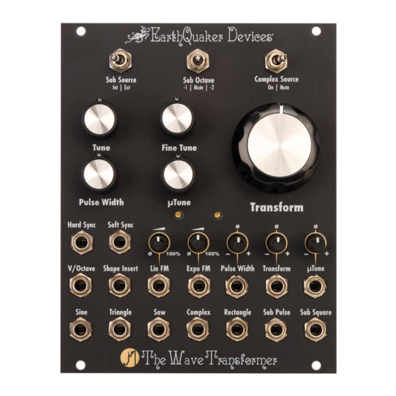
- Page 1 The Wave Transformer Eurorack Module - Transfiguration Oscillator...
- Page 2 INTRO Hey there, friendo! Congrats on the purchase of The Wave Transformer Transfiguration Oscillator. The Wave Transformer is a vintage-voiced voltage-controlled oscillator with over 8 octaves of accurate pitch tracking. It has 7 simultaneous wave outputs, including a unique Complex output.
- Page 3 OVER +/-10. PLEASE USE CARE WHEN OPERATING THIS EQUIPMENT, AS HIGH SIGNAL LEVELS CAN DAMAGE YOUR AUDIO EQUIPMENT OR YOUR HEARING! *EARTHQUAKER DEVICES DOES NOT IMPLY NOR ASSUME ANY RESPONSIBILITY FOR HARM TO ANY PERSON OR DAMAGE TO ANY DEVICE OR OBJECT AS A RESULT OF THE USE OF THIS MODULE.* THIS DEVICE COMPLIES WITH PART 15 OF THE FCC RULES.
-
Page 4: Tech Specs
TECH SPECS • Dimensions: 20HP / Max Depth: 1 inch (25.4 mm) • Current Draw: 90 mA max from the +12v rail, 90 mA max from the -12v rail • Standard 10-pin Eurorack power connector with a marking to notate the negative pins •... -
Page 5: Installation
INSTALLATION Power off and unplug your Eurorack case or power supply and locate 20HP of empty space within your system. Connect the 10-pin end of the included ribbon cable to the power pin header on the back of your module so the red stripe on the cable is oriented towards the words “Red Stripe”... -
Page 6: Panel Controls
PANEL CONTROLS SUB SOURCE Selects either the internal oscillator or the signal patched into the Shape Insert jack for use in generating sub octaves. This control affects the Complex, Sub Pulse and Sub Square outputs. Leave this set to “INT” unless you are tracking an external source. - Page 7 PANEL CONTROLS (CONT.) COMPLEX SOURCE Selects between muting and unmuting the source wave for the Complex output. Leaving the source wave unmuted allows you to hear the waveform morph from the original wave through multiple iterations until it reaches maximum harmonic complexity. Muting the source waveform means that the Complex output will be silent if the Transform panel control is fully counterclockwise, and...
-
Page 8: Pulse Width
PANEL CONTROLS (CONT.) μTUNE (MICRO TUNE) Ultra fine control of the oscillator, spanning approximately 25 cents. PULSE WIDTH Varies the pulse width of the Rectangle output between 0% and 100%. At 0% or 100% Pulse Width, the Rectangle output is silent. TRANSFORM Morphs the Complex output from a triangle wave through multiple iterations into a strange... - Page 9 SYNC TRACKING IS HIGHLY DEPENDENT ON THE CHARACTERISTICS AND FREQUENCY OF THE INCOMING SIGNAL, AS WELL AS THE FREQUENCY OF THE WAVE TRANSFORMER.
- Page 10 INPUTS (CONT.) V/OCTAVE Accepts traditional volt/octave CV to control pitch. Over 8 octaves of accurate pitch tracking starting at A -1 (13.75Hz). SHAPE INSERT Insert another waveform or modular-level signal to be mutated by the Transform circuit. The new waveform changes the results heard at the Complex output.
- Page 11 INPUTS (CONT.) LIN FM Accepts +/–5 volts audio signals. Allows linear frequency modulation, where an increase or decrease in control voltage respectively increases or decreases the pitch of the oscillator in a manner that has a linear relationship to the incoming voltage. The input is AC coupled to block DC signals in order to reduce any pitch offset during use of frequency modulation.
- Page 12 INPUTS (CONT.) EXPO FM Accepts +/–10 volts. Allows linear frequency modulation, where an increase or decrease in control voltage respectively increases or decreases the pitch of the oscillator in a manner that has an exponential relationship to the incoming voltage. That is to say that with each volt of increase at the input the audio frequency will double.
- Page 13 INPUTS (CONT.) PULSE WIDTH CV INPUT Accepts +/–5 volts. Allows control of the pulse width of the Rectangle output from 0-100% duty cycle. Pulse Width can be modulated with DC control voltages and audio signals. Note: Settings of 0% or 100% will result in silence at the Pulse Width output.
- Page 14 INPUTS (CONT.) TRANSFORM CV INPUT Accepts 0-5 volts. Controls the Transform circuit. This CV input is added to the Transform panel control. Use the panel control to set the default transformation from which you’d like to modulate. This input has an inverting attenuator located above the input jack.
- Page 15 INPUTS (CONT.) μTUNE CV INPUT Accepts +/–10 volts. This is an exponential CV input that allows precise modulation of the oscillator pitch. An increase in voltage of 10 volts will increase the pitch by around 7 semitones. This input can be used to sequence precise pitch bends, adding pitch instability with a random voltage source, or sequencing tiny changes in pitch for drone or microtonal music.
- Page 16 OUTPUTS SINE +/–5 volts. The most basic waveform, it sounds smooth and clean, and is made up of only the fundamental frequency. TRIANGLE +/–5 volts. A bit pointier than the Sine wave, the Triangle wave has a little bit more buzz to it and contains a combination of the fundamental frequency and odd order harmonic frequencies that taper off rather quickly.
- Page 17 OUTPUTS (CONT.) COMPLEX Up to +/–10 volts. This strange and novel output varies between a simple waveform (triangle, unless you patch a signal into the Shape Insert jack) and a complex transformation of the harmonic structure of the original waveform. It contains a unique mixture of the fundamental frequency, odd order harmonics, even order harmonics and subharmonics.
- Page 18 OUTPUTS (CONT.) Using the Complex Source panel control to mute the source wave will cause the Complex output to be silent if the Transform panel control is fully counterclockwise, and no CV is present at the Transform CV input. This allows the Transform circuit to act as a harmonic gate/VCA.
- Page 19 OUTPUTS (CONT.) SUB PULSE +/–5 volts. 25% duty cycle sub octave signal that is 1 octave lower than the source signal. The source signal is selected by the Sub Source switch. When set to “INT”, the sub octave is derived from the internal oscillator. When set to “EXT”, the sub octave is derived from the signal that has been patched to the Shape Insert jack.
- Page 20 OUTPUTS (CONT.) SUB SQUARE +/–5 volts. A sub octave square wave that is either 1 or 2 octaves down from the source signal, depending on the Sub Octave setting. The source signal is selected by the Sub Source switch. When set to “INT”, the sub octave is derived from the internal oscillator.
-
Page 21: Warranty
WARRANTY We will fix any of our devices for as long as we are in business. There is never a charge unless the circuit board needs to be replaced due to user damage such as a failed non-factory repair, incorrect power supply, reverse voltage, modification, water damage, etc.
Need help?
Do you have a question about the The Wave Transformer and is the answer not in the manual?
Questions and answers