
Related Manuals for Colasit CHVS 63-250


Summary of Contents for Colasit CHVS 63-250
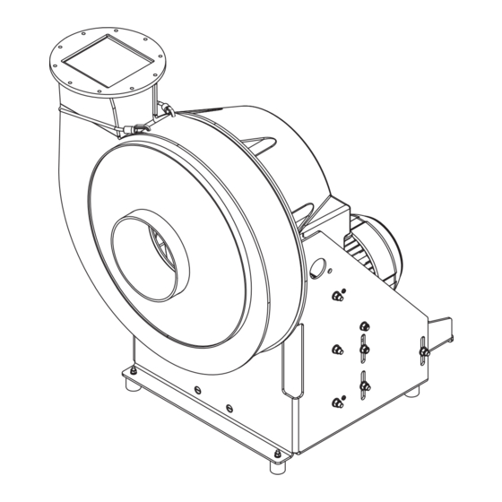
- Page 1 CHVS 63-250 Centrifugal fan with V-belt drive Your point of contact: Colasit Representative Street Location Version 1.0-en | 01/2024...
- Page 2 Description Date Name 1-en First version published. 1/15/2024 A. Roth Document identification Translation of the original German operating instructions. Colasit TD-000863 Contact information Manufacturer COLASIT AG Faulenbachweg 63 CH-3700 Spiez E-mail: fans@colasit.com Website: www.colasit.com Phone: +41 (0)33 655 61 61...
-
Page 3: Table Of Contents
Signs and warning symbols on the fan with V-belt drive ........Options and accessories ..................4.3.1 Vibration absorbers (round isolators) for floor mounting......4.3.2 Sleeves ...................... 4.3.3 Sleeves with flange ..................4.3.4 Flange connections..................4.3.5 Condensate drain..................4.3.6 Isolation switch................... CHVS 63-250 | Version 1.0-en 3 / 84... - Page 4 Frequency converter (FC) installation options ........... 7.3.2 Frequency converter (FC) parameterization ..........7.3.3 Connecting the electric motor to a frequency converter (FC) ....Connecting the electric motor................. Installing the belt guard ..................4 / 84 CHVS 63-250 | Version 1.0-en...
- Page 5 11.10Replacing the felt ring seal ..................11.11Replacing the drive belt..................11.12Measuring and setting belt tension................. Removal from service, disposal, and recycling ..........12.1 Safety instructions ....................12.2 Environmental protection..................12.3 Removal from service..................... 12.4 Disposal instructions ....................CHVS 63-250 | Version 1.0-en 5 / 84...
- Page 6 Table of contents EU - Declaration of conformity................Index ........................6 / 84 CHVS 63-250 | Version 1.0-en...
-
Page 7: Operating Instruction Information
Design notes For the sake of simplification, in these operating instructions, • the company Colasit AG is referred to as the “manufacturer,” • all sizes (CHVS 63-250) are generally referred to as the “fan,” • “frequency converter” is abbreviated as “FC,”... -
Page 8: Copyright
Copyright These operating instructions are protected by copyright. © COLASIT AG. All rights reserved. The use and distribution of the operating instructions is permitted in the context of using the fan. Any other use is only permitted with the written consent of the manufacturer. -
Page 9: Additional Safety Instructions
• For independent assessment, the operator is to consult the pertinent available resistance lists for plastics. The SIMCHEM guide is found on the manufacturer's website (www.colasit.com). CHVS 63-250 | Version 1.0-en 9 / 84... - Page 10 • The operating point (see characteristic map on the technical data sheet) shall be above the minimum permissible conveyed volume. • So that no or minimal conveyed medium escapes from the impeller hub, 10 / 84 CHVS 63-250 | Version 1.0-en...
-
Page 11: Reasonably Foreseeable Misuse
• Removal of components or tampering with components that ensure safe and proper function of the fan (e.g. vibration absorbers, splinter protection, sleeves, protective grid). • Improperly conducted maintenance work. • Use of non-original spare parts. CHVS 63-250 | Version 1.0-en 11 / 84... -
Page 12: Equipment Limits
The fan is designed and manufactured in accordance with the state of the art and the recognized technical safety regulations. Residual risks nevertheless re- main. They are indicated by safety instructions in these operating instructions and require the user to proceed with caution. 12 / 84 CHVS 63-250 | Version 1.0-en... -
Page 13: Target Groups And Personnel Requirements
• Ensure that the fan is always in a technically sound condition under obser- vance of the maintenance intervals per these operating instructions. • Initiate and verify that the function and integrity of all fan safeguards are checked regularly. CHVS 63-250 | Version 1.0-en 13 / 84... -
Page 14: Transport Personnel
• All work on the fan’s electrical components may only be carried out by elec- tricians. • The fan may only be connected to the frequency converter by an electrician • after its operating instructions have been read and understood, 14 / 84 CHVS 63-250 | Version 1.0-en... -
Page 15: Operating Personnel
• The same requirements apply as for the mounting personnel Chap. 2.3.3 [} 14]. • An electrician is responsible for carrying out maintenance and repair work and for switching off and safely disconnecting the power supply from the fan. CHVS 63-250 | Version 1.0-en 15 / 84... -
Page 16: Essential Safety Instructions
▪ Conditions for prevention of the danger... Measures for prevention of the danger... This warning instruction informs of a dangerous situation that can damage the fan or or lead to other material damage. 16 / 84 CHVS 63-250 | Version 1.0-en... -
Page 17: Personal Protective Equipment
Work gloves for protection from injuries, burns, or contact with ag- gressive, toxic residues of the conveyed medium. Safety shoes for protection from crushing and from falling parts as well as slips and falls on slick surfaces. CHVS 63-250 | Version 1.0-en 17 / 84... -
Page 18: Mechanical Hazards
Establish an electrically safe work condition before beginning work. Promptly rectify any defects discovered in the electrical components and wiring of the fan. Eliminate moisture from current-carrying components to avoid a short cir- cuit. 18 / 84 CHVS 63-250 | Version 1.0-en... -
Page 19: Danger Due To Electromagnetic Interferences
Wear protective gloves when working on the fan or electric motor. When mounting the fan, observe the minimum distance between the fan cowl of the electric motor and neighboring components or walls Chap. 6.2 [} 34]. CHVS 63-250 | Version 1.0-en 19 / 84... -
Page 20: Noise Hazard
Actions to take in an emergency Explosion or melting of the plastic components during fan operation constitutes an emergency situation. Possible causes (due to use in a manner other than that intended): 20 / 84 CHVS 63-250 | Version 1.0-en... - Page 21 Do not attempt to extinguish in confined, small, or enclosed spaces. Instead, fight fire from outside through open door. Do not access area where fire occurred until it has been thoroughly venti- lated. CHVS 63-250 | Version 1.0-en 21 / 84...
-
Page 22: Structure And Function
Function description In the centrifugal fan, a gaseous medium is drawn in through the inlet connec- tion in the direction of the motor axis and deflected radially by the rotating im- peller. 22 / 84 CHVS 63-250 | Version 1.0-en... -
Page 23: Signs And Warning Symbols On The Fan With V-Belt Drive
Test deflection 9.0 mm Frequency 69 Hz Vitesse maximale d´utilisation à ne dépasser! COLASIT AG Faulenbachweg 63, CH-3700 Spiez Phone: +41 (0)33 655 61 61 • www.colasit.ch • info@colasit.ch Type CHVS 250 Serial No. 234567_10_1 Casing material Pos. LG0 (Eurovent) Date 10.2023 Impeller material... -
Page 24: Options And Accessories
• Outlet side with flange and worm-gear hose clamp. • Executions: See accessories for the CHVS 63-250 on the manufacturer’s website (www.colasit.com). • Permissible distance between fan connections and ductwork Chap. 6.6 [} 38]. Fig. 5: Sleeve installation locations 24 / 84 CHVS 63-250 | Version 1.0-en... -
Page 25: Sleeves With Flange
• “V” for connection to siphon. Suit- able for socket welds. • For instructions on retroactive mount- ing as well as siphon dimensioning Chap. 6.7 [} 39]. Fig. 8: Casing drain on condensate drain CHVS 63-250 | Version 1.0-en 25 / 84... -
Page 26: Isolation Switch
• Optional accessory. • For setting the nominal speed on the frequency converter (FC) according to the technical data sheet. • FC parameterization Chap. 7.3 [} 44]. Fig. 11: Speed adjustment potentiometer (example image) 26 / 84 CHVS 63-250 | Version 1.0-en... -
Page 27: Protective Grid
• Use with hazardous, aggressive conveyed media when the fan is operated in an overpressure condi- tion. • Wear part • For mounting instructions Chap. 11.9 [} 70]. Fig. 13: Lip seal (single layer) CHVS 63-250 | Version 1.0-en 27 / 84... -
Page 28: Back Suction For Lip Seal
• Leakage near the hub passage is directed to the suction connection via a tube and guided back into the main flow. • For mounting instructions Chap. 11.9 [} 70]. Fig. 15: Back suction 28 / 84 CHVS 63-250 | Version 1.0-en... -
Page 29: Sealing Gas For Lip Seal
• Use with hazardous, aggressive conveyed media when the fan is operated in an overpressure condi- tion. • Wear part • For mounting instructions Chap. 11.10 [} 71]. Fig. 17: Hub seal felt ring CHVS 63-250 | Version 1.0-en 29 / 84... -
Page 30: Impeller Back-Plates
4 | Structure and function 4.3.14 Impeller back-plates • Optional. • Used in combination with a hub seal and/or in high humidity. • Impeller back-plates are welded onto the impeller before balancing. Fig. 18: Impeller back-plates 30 / 84 CHVS 63-250 | Version 1.0-en... -
Page 31: Transport
Do not receive delivery, or doing so only conditionally. Record transport damage (photos). Note the extent of the damage on the transport paperwork or on the trans- port company’s bill of lading. File a complaint immediately. CHVS 63-250 | Version 1.0-en 31 / 84... -
Page 32: Packing
• Lift package slightly and check that it hangs level. Fig. 19: Package with lifting eye bolts • Let down and adjust a package that doesn’t hang level: Shorten or lengthen legs on one side appropriately until all legs are loaded equally. 32 / 84 CHVS 63-250 | Version 1.0-en... -
Page 33: Transport By Pallet Stacker Or Forklift
A package on a pallet can be transported by pallet stacker or forklift under the following conditions: • Forks inserted under the pallet as depicted such that they stick out from the opposite side. Fig. 22: Package on transport pallet CHVS 63-250 | Version 1.0-en 33 / 84... -
Page 34: Mechanical Installation
Foundation (baseplate) or mounting surface shall meet the following require- ments: • Vibration resistant • Flat surface • Suitable for absorption of static and dynamic loads. • For calculations for the mounting parts, assume four times the fan weight. 34 / 84 CHVS 63-250 | Version 1.0-en... -
Page 35: V-Belt Drive - Check Proper Mounting
The V-belt drive shall always be guarded against access with the supplied hood. The settings for the V-belt drive are • specified on the belt plate and • depend on the belt type and are specific to the fan supplied. CHVS 63-250 | Version 1.0-en 35 / 84... -
Page 36: Splinter Protection - Check Proper Mounting
• Both snap hooks (2) are en- gaged in the eyes. • The rubber band lies in notch (3) of the welding edge. Fig. 25: Proper mounting of the splinter protection 36 / 84 CHVS 63-250 | Version 1.0-en... -
Page 37: Vibration Absorbers Mounting
Fig. 26: Fastening recommendation for floor mounting 1. Transfer fan support hole pattern to the foundation (baseplate). Hole pattern dimensioning according to technical data sheet. 2. Install anchoring elements (anchors) according to supplier’s instructions. CHVS 63-250 | Version 1.0-en 37 / 84... -
Page 38: Connecting Fan To Ductwork
Check beforehand: • Turn the impeller by hand and check that it is smooth running. • Check the fan and ductwork for tools left behind, mounting residues, or for- eign objects. 38 / 84 CHVS 63-250 | Version 1.0-en... -
Page 39: Connecting Condensate Drain To Siphon
Environmental damage due to toxic condensate If possible, direct condensate downstream of the siphon back into the process. Collect condensate in the collecting container and dispose of according to regulations. Fig. 28: Proper position of the casing drain CHVS 63-250 | Version 1.0-en 39 / 84... -
Page 40: Siphon Calculations And Execution
If the siphon height “h“ is not observed, the condensate will not drain and will be directed to the fan. When planning for and mounting the siphon, observe a minimum installation height of 2 x H. 40 / 84 CHVS 63-250 | Version 1.0-en... -
Page 41: Final Inspection
(baseplate) or mounting surface are tight. • Check splinter protection Chap. 6.4 [} 36]. • If present in ductwork: • Shut-off dampers for inlet and outlet connections are closed. • Service openings are shut. CHVS 63-250 | Version 1.0-en 41 / 84... -
Page 42: Electrical Installation
The isolation switch is only a protective device for disconnecting the fan from electrical power during mounting, maintenance, or repair work and not to turn the fan on and off in the context of operation. The isolation switch 42 / 84 CHVS 63-250 | Version 1.0-en... -
Page 43: Motor Protection Switch Installation
When connected to a FC, shutdown should be performed by the "safe stop" safety function. This ensures that no residual voltage is applied to the motor windings and that the electric motor can cool down as quickly as possible. CHVS 63-250 | Version 1.0-en 43 / 84... -
Page 44: Starting Current Limiter
▪ If long cable shields are not connected/grounded, high contact voltages can occur during operation. Connect cable shields of motor connection cables and signal lines to a com- mon reference potential. Do not use protective earth connections for shielding purposes. 44 / 84 CHVS 63-250 | Version 1.0-en... -
Page 45: Frequency Converter (Fc) Installation Options
7.3.1 Frequency converter (FC) installation options For CHVS 63-250 type centrifugal fans, different executions of electric motors (IM, PM, EC) can be selected as a drive: • IM ... Standard asynchronous motor/three-phase motor •... -
Page 46: Frequency Converter (Fc) Parameterization
To avoid an FC error message, a longer acceleration/braking time could be nec- essary. Parameterization for PM motors Parameterization for PM motors differs significantly from three-phase motors. The FC and motor manufacturers offer support for this. 46 / 84 CHVS 63-250 | Version 1.0-en... -
Page 47: Connecting The Electric Motor To A Frequency Converter (Fc)
Secure the motor connection cable to the motor terminal box with an EMC cable gland. • Strip the cable end appropriately so that contact can be made with the cable shield. Connect the motor connection cable to the electric motor Connecting the electric motor. CHVS 63-250 | Version 1.0-en 47 / 84... -
Page 48: Connecting The Electric Motor
• Compare the mains voltage and mains frequency with the information on the motor nameplate and determine the connection type of the electric mo- tor (star or delta connection). Fig. 32: Terminal assignment for delta and star connection 48 / 84 CHVS 63-250 | Version 1.0-en... -
Page 49: Installing The Belt Guard
2. Install four spacers between the support and belt guard (see details). Fig. 33: Installing the belt guard Final inspection • Verify mains and motor connections with motor nameplate data. CHVS 63-250 | Version 1.0-en 49 / 84... - Page 50 • Check and record important FC parameters and settings: Maximum output frequency, V/f characteristic curves, acceleration and braking times Instructions for frequency converter (FC) use. If required for control and placement in service, connect an external control unit to the FC. 50 / 84 CHVS 63-250 | Version 1.0-en...
-
Page 51: Placement In Service
Functional test of the frequency converter (FC, optional accessory) Procedure: • Test start/stop and acceleration behavior starting at a low frequency (25 Hz). • Increase fan speed from minimum to maximum speed Chap. 7.3.2 [} 46] CHVS 63-250 | Version 1.0-en 51 / 84... -
Page 52: Conduct Test Run
ISO 14694: Status Category Permissible vibration when flexibly mounted (effective value/RMS) [mm/s] Start-up BV-2 BV-3 Alarm BV-2 14,0 BV-3 11,8 Shutdown BV-2 BV-3 12,5 * Establish based on historical limit values. 52 / 84 CHVS 63-250 | Version 1.0-en... - Page 53 • For fan with V-belt drive: Check belt tension Measuring and setting belt ten- sion. • Create a test report during initial commissioning. • Leakage value: The leakage value of the supplied fan can be requested from the distributor. CHVS 63-250 | Version 1.0-en 53 / 84...
-
Page 54: Operation
• Keep the installation site of the fan clean. Observe cleaning interval and adjust if necessary Chap. 10.2 [} 55]. 54 / 84 CHVS 63-250 | Version 1.0-en... -
Page 55: Maintenance
Only clean the fan with a damp cloth. 10.2 Maintenance table The maintenance intervals (W/weekly, M/monthly, 6M/semi-annually and 12M/ annually) are to be adapted to the current operating conditions of the fan as de- termined by the customer. CHVS 63-250 | Version 1.0-en 55 / 84... -
Page 56: Maintenance Work
• Back suction functional (tube free of contamination)? • Sealing gas available? • For loose screw connections. • Smooth operation of fan: • For irregular running, check for vibration or noise Chap. 8.2.3 [} 52]. 56 / 84 CHVS 63-250 | Version 1.0-en... -
Page 57: Inside Inspection
The mechanical and electrical functionality of the fan are assessed in the annual inspection, and its continued operation is ensured. This also applies in the event of extensive downtime. Check during outside inspection • Cracking: Fan housing, vibration absorber • Noise: Motor bearings CHVS 63-250 | Version 1.0-en 57 / 84... - Page 58 Check belt tension and adjust it if necessary Measuring and setting belt tension. • If necessary, conduct outside and inside cleaning. Assembly and final inspection • Proper mounting of the splinter protection Chap. 6.4 [} 36]. 58 / 84 CHVS 63-250 | Version 1.0-en...
- Page 59 Maintenance | 10 • Fixed position of all screw connections. • Fixed position of all fastening elements (anchors) in the foundation (baseplate). • Short test run, checking for vibration and noise. CHVS 63-250 | Version 1.0-en 59 / 84...
-
Page 60: Repair
Observe minimum dis- work. tance between fan connection and damper valve or duct bends (L > 3 x duct Ø). Drive belt slips. Check belt tension Tension the drive belt Chap. 11.12 [} 73] Chap. 11.11 [} 72] 60 / 84 CHVS 63-250 | Version 1.0-en... - Page 61 Chap. 7.2.2 [} 43]. tripping device, Check FC parameters. Parameterize FC prop- or FC switches erly. off. Faulty motor connec- Measure current draw. Check motor connec- tion. tion (star/delta) Con- necting the electric motor. CHVS 63-250 | Version 1.0-en 61 / 84...
- Page 62 Chap. 2.2.1 [} 9] conveyed medium and plastic resistance. Chap. 2.2.2 [} 11]. Measure temperature Adjust operating con- of the conveyed ditions to intended use medium. Chap. 2.2.1 [} 9]. Check operating point. Check environmental conditions. 62 / 84 CHVS 63-250 | Version 1.0-en...
- Page 63 Fan/electric motor no Consult with point of system changes. longer meeting the op- contact (see title erating point. page). FC does not reach re- Check FC. Use a suitable FC. quired voltage. CHVS 63-250 | Version 1.0-en 63 / 84...
- Page 64 FC machining (bearing and casing of the elec- operation; see FC currents). tric motor. manufacturer’s guid- ance. Check EMC guidelines. Use current-insulated roller bearings or ce- ramic hybrid bearings. 64 / 84 CHVS 63-250 | Version 1.0-en...
-
Page 65: Spare Parts And Wear Parts
• or of the option or accessory Chap. 4.3 [} 24]. Have spare parts and wear parts for the impeller or hub seal available: Designation Spare part Wear part Impeller Hub end cap CHVS 63-250 | Version 1.0-en 65 / 84... -
Page 66: Preparation For Repairs
Special centering pieces are needed for proper installation and alignment of the flange bearing and the impeller to the casing and rear plate. Contact your Colasit distributor for details and a comprehensive installation manual. Prepare the fan for repairs (impeller, electric motor, hub seal, etc.) as follows: Observe safety instructions Chap. -
Page 67: Check Impeller
Torque the fastening screws of the casing in accordance with the following table. Fan/size Fastener threads Max. tightening torque [Nm] CHVS 63-250 11.7 Impeller exchange Conditions: • Fan has been prepared for repairs Chap. 11.4 [} 66]. CHVS 63-250 | Version 1.0-en 67 / 84... - Page 68 • Tighten the impeller with the fastening screw, with RIPP LOCK® for fas- tener security, in accordance with the following table. Flange bearing shaft Fastener threads Max. tightening torque diameter [mm] [Nm] 68 / 84 CHVS 63-250 | Version 1.0-en...
-
Page 69: Electric Motor Exchange
Use the lifting eye bolts on the electric motor for this purpose. 8. Install the new electric motor. 9. Align and tension the belt Chap. 11.12 [} 73]. Fig. 38: Removing the belt pulley from the motor shaft CHVS 63-250 | Version 1.0-en 69 / 84... -
Page 70: Lip Seal (Option) Replacement
4. Center the housing of the lip seal to the rear plate and impeller hub and screw it to the rear plate. 5. Pre-mount the rear plate to the sup- port (only finger-tighten the screws). Fig. 39: Replacing the lip seal 70 / 84 CHVS 63-250 | Version 1.0-en... -
Page 71: 11.10 Replacing The Felt Ring Seal
11. Install the belt guard. Installation tools Special centering pieces are necessary for proper installation of the double-layer lip seal. Contact your Colasit distributor for details and a comprehensive installa- tion manual. Important The impeller should turn freely by hand after mounting. -
Page 72: 11.11 Replacing The Drive Belt
Replace them if they are worn. 3. Tension the drive belt using the two threaded rods. 4. Install the belt guard. 5. Conduct test run Conduct test run. Fig. 41: Replacing the drive belt 72 / 84 CHVS 63-250 | Version 1.0-en... -
Page 73: 11.12 Measuring And Setting Belt Tension
• Tension the drive belt if necessary until the specified value is reached. Fig. 42: Measuring belt tension The belt span is the free section of belt between two belt pulleys that is not rest- ing on the pulleys. CHVS 63-250 | Version 1.0-en 73 / 84... -
Page 74: Removal From Service, Disposal, And Recycling
Watch for deposits and condensate of the conveyed medium in the fan and ductwork. Procedure: • Switch off fan and FC (option) and prepare them for removal: • Allow to cool down. 74 / 84 CHVS 63-250 | Version 1.0-en... -
Page 75: Disposal Instructions
• Separate the fan components into material groups and dispose of them sep- arately: • Metals • Plastics • Electrical components Dispose of plastic parts contaminated by conveyed media that are harmful to health and the environment as special waste. CHVS 63-250 | Version 1.0-en 75 / 84... - Page 76 3700 Spiez Switzerland declare under our sole responsibility Plastic industrial fan that the product of the series CHVS 63 CHVS 63-250 with V-belt drive CHVS 90 CHVS 125 CHVS 160 CHVS 200 CHVS 250 to which this declaration refers is in conformity with the provisions of the follow-...
- Page 77 Health protection 13 Direction of rotation arrow 51 Hoisting gear 31, 32, 69 Disposable packing 32 Hole pattern 37 Disposal 7, 14, 74, 75 Hose clamps 39, 64 Disposal instructions 32, 75 CHVS 63-250 | Version 1.0-en 77 / 84...
- Page 78 Protective equipment 13, 14, 17, 18, 20, Misuse 11 31, 34, 55, 74 Motor 11, 37 Protective grid 11, 20, 27, 56, 58 Motor axis 22 21 Motor bearings 12, 44, 58, 70 78 / 84 CHVS 63-250 | Version 1.0-en...
- Page 79 Supply air duct 51, 55, 66 Support 19, 22, 33, 42, 46, 49, 56, 58, 67, 74, 75 Supports 34, 38 Swinging movements 31 Terminal 12 Terms and conditions 32 Test report 53, 58 CHVS 63-250 | Version 1.0-en 79 / 84...
- Page 80 Notes Notes 80 / 84 CHVS 63-250 | Version 1.0-en...
- Page 81 Notes CHVS 63-250 | Version 1.0-en 81 / 84...
- Page 82 Notes 82 / 84 CHVS 63-250 | Version 1.0-en...
- Page 83 Notes CHVS 63-250 | Version 1.0-en 83 / 84...
- Page 84 - since 1945 - When it comes to thermoplastics, Colasit AG is one of the world's leading brands in fan and system engineering. Our qualified staff impress with technical expertise and great dedication, guaranteeing you the highest quality on all five continents.
Need help?
Do you have a question about the CHVS 63-250 and is the answer not in the manual?
Questions and answers