
Related Manuals for Xantech SPLCD64G

Summary of Contents for Xantech SPLCD64G
- Page 1 INSTALLATION & PROGRAMMING MANUAL SMARTPAD LCD™ TOUCH-SCREEN PANEL CONTROLLER Models SPLCD39G, SPLCD64G & SPLCD64V SPLCD39G SPLCD64V...
-
Page 2: Safety Instructions - Read Before Operating Equipment
19. FCC Notice – This device complies with Part 15 of the FCC Rules. Operation is subject to the following two conditions: (1) this device may not cause harmful interference, and (2) this device must accept any interference received, including interference that may cause undesired operation. DO NOT REMOVE COVER (OR BACK) NO USER-SERVICEABLE PARTS INSIDE © 2008 Xantech Corporation SmartPad LCD™... -
Page 3: Table Of Contents
SECTION 2: INSTALLATION & CONNECTIONS ... 14 INSTALLATION... 14 Back Box Mounting Instructions ... 14 SPLCD POWER SUPPLY AND INPUT/OUTPUT WIRING INSTRUCTIONS... 16 POWER SUPPLY & STANDARD XANTECH IR OUTPUT BUS WIRING... 16 Power Supply Wiring ... 17 IR Wiring... 17 External IR Input Wiring... 18 MRC CONTROLLER AND EXPANSION PORT WIRING... - Page 4 LEARNING IR COMMANDS (CREATING PALETTE FILES) ... 43 Built-In IR Code Library... 43 TESTING IR COMMANDS IN THE IR LIBRARY... 44 IMPORTING XANTECH LEGACY IR PALETTE FILES... 45 Learning IR Commands (XIR2) ... 45 Finding the Optimal Positioning of the Teaching Remote ...45 Using the Palette Editor ...46...
- Page 5 RS232 Port Default Settings... 70 RS232 Port Router Settings ... 70 SECTION 7: APPENDIX ... 71 INTERFACING SPLCD WITH MRC44 (IR CONTROL) & MRC88 (MRC88 EMULATION)... 71 MRC88 EMULATION MODE: FEATURE DESCRIPTION & PROGRAMMING ... 71 © 2008 Xantech Corporation Page: 5...
- Page 6 TRANSPARENT BUTTON GTL OVERLAY FEATURE ... 81 Placing Transparent Button GTL’s in Full Screen Video Mode ...81 Transparent Button GTL and Music Server Integration...82 CUSTOM BACKGROUNDS AND TRANSPARENT GTL’S... 83 Importing Pictures as Custom Backgrounds ...83 © 2008 Xantech Corporation SmartPad LCD™...
-
Page 7: Section 1: General Information & Features
As with the previous models of SmartPad Keypads, these new touchpanels are designed to be stand-alone controllers with the ability to output IR commands onto the standard Xantech four-wire IR Bus as well as receive (and pass-through) IR commands via the built-in IR receiver. These new touchpanels also have the ability to receive and transmit RS232 commands for a wide range of control options. -
Page 8: System Overview
Simply connecting a power supply and then connecting the SmartPad LCD outputs to any standard Xantech IR bus, makes a complete IR Repeater System. By adding the optional RS422232 converter, you can literally control almost any Audio Video or Home Automation component. The SmartPad LCD or SPLCD is also directly compatible with the MRC-88 Whole-house Audio Video Entertainment System. -
Page 9: Smartpad Lcd Features
Upper and Lower Viewing Angles: Software Programmable for exact viewing placement Programmable Backlight Control: Selectable Time-Out for LCD backlight Standard Xantech IR Bus Output: Allows for easy interface to existing IR networks Internal IR Code Library: Built in IR Code Library. Contains all Major Brand Component IR commands. No need to ‘learn’... -
Page 10: Smartpad Lcd Panel And Feature Descriptions
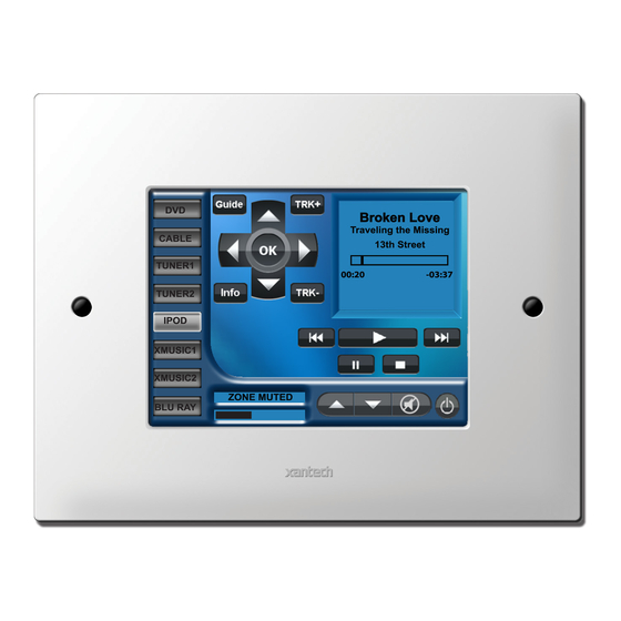
Page: 10 SmartPad LCD™ SMARTPAD LCD PANEL AND FEATURE DESCRIPTIONS Figure 2a – SmartPad LCD™ Model SPLCD39G – Front Panel Features and Functions Figure 2b – SmartPad LCD™ Model SPLCD64G & SPLCD64V– Front Panel Features and Functions © 2008 Xantech Corporation... -
Page 11: Splcd Front Panel Features And Connections
11. LCD Contrast Control. Adjusts the Contrast of the SPLCD screen. Slowly turn clockwise to increase contrast. 12. Bezel Mounting Clips (4). Guide clips for mounting the Front Bezel onto the SPLCD. © 2008 Xantech Corporation Page: 11... -
Page 12: Splcd Rear Panel Features And Connections
17. IR In-Zone. 2-Terminal WECO style socket - Zone IR out for local ‘In-Zone’ emitter out. Used for IR control of equipment in the same location as the SPLCD. Output equivalent to that of Xantech Amplified Connecting blocks. 100mA peak output. Connect directly to Emitter or to Xantech Connecting Blocks (789- 44 or 791-44). - Page 13 12VDC STATUS output from SPLCD to remote device. (Universal Dragon required to configure terminal as a Status Input or Status Output). d. IR BUS Pin: IR Output from SPLCD connects to a Xantech Connecting Block (SPLCDCB100, 789-44, 791-44, CB60 etc.) Can drive a single emitter up to 2000’ on 18AWG.
-
Page 14: Section 2: Installation & Connections
3. Using a hole saw or other cutting tool, carefully cut along the inner guide lines of the Mounting Template as shown in Figure 5 below. Mounting Template Part No. 08187158 08187157 08187157 © 2008 Xantech Corporation SmartPad LCD™ Cutout Dimensions 5.50” X 6.50” 7.63” X 9.49” 7.63” X 9.49”... - Page 15 Figure 6 – Back Box Cable Access Point (Back-Box Rear View) 6. Pull all cables through the wall opening and desired punch-out hole in the Back Box. Figure 5 – Cutting the Mounting Hole © 2008 Xantech Corporation Page: 15...
-
Page 16: Splcd Power Supply And Input/Output Wiring Instructions
SPLCD POWER SUPPLY AND INPUT/OUTPUT WIRING INSTRUCTIONS The SmartPad LCD can be interfaced in numerous fashions; Standard Xantech IR Bus, RS232, Direct Connect to MRC88, External IR Input, and Local IR (Emitter Output). The following sections address each of these wiring configurations. -
Page 17: Power Supply Wiring
Xantech Model# SPLCDPS1 is a 16VDC Power Supply @ 1.5A that can power for one SPLCD. • Xantech Model# SPLCDPS4 is a 16V DC Power Supply @ 3.12A that can power up to four SPLCD’s. Power Supply With a Connecting Block 1. -
Page 18: External Ir Input Wiring
Connect either terminal to the GND of the external IR Receiver. • IR Input: Connect to the IR Output of an IR Receiver such as Xantech 780, 291, 480, 490 Series or other compatible device. Pull 3-conductor 18-24AWG stranded non-shielded wire (4-Conductor if using the Status line) from the SPLCD location to the IR Receiver location. -
Page 19: Mrc Controller And Expansion Port Wiring
SPLCD or MRC88KP in line. (Four keypads max per zone.) 2. Remove the Zone Termination Jumper (Figure 3 – 15) from all but the last keypad in the daisy chain. Figure 9 – External IR Input Wiring © 2008 Xantech Corporation Page: 19... -
Page 20: Serial Rs422/232 Port Wiring
1. Using CAT5 cable terminated in RJ45 connectors in a pin to pin configuration, connect the Serial Port on the SPLCD Rear Panel to the Serial Port on a Xantech RS422232. (Figure 10) NOTE 1: The RS422232 Converter (sold separately) and a 12VDC Power Supply (Xantech model 781ERGPS) should be located within 30ft of the RS232 device to be controlled. -
Page 21: Ir In Zone
IR In Zone allows connection of emitters directly to the SPLCD to control components in the same general area as the SPLCD. 1. Cut the 3.5mm mini plug off the end of a Xantech IR emitter. 2. Connect the IR OUT Terminal on the SPLCD Rear Panel to the white stripe wire on the emitter wire and connect the GND Terminal to the black wire on the emitter cable, using the included 2-conductor screw- type Removable Connector. -
Page 22: Installing The Splcd Into The Back-Box
6. Push the Bezel gently into the Mounting Clips until it is flush with the wall making sure the side tabs go through the slots on the metal bracket. Figure 12 – Installing SPLCD into Back Box © 2008 Xantech Corporation SmartPad LCD™... -
Page 23: Section 3: Maintenance & Calibration
If the unit is powered ON (active), simply press and hold an area of the SPLCD Display with no active GTL’s. While holding this area, gently wipe the rest of the display as noted above. © 2008 Xantech Corporation Page: 23... -
Page 24: Section 4: Programming The Smartpad Lcd
PC from Universal Dragon. The Install Wizard will try to run as soon as the PC is connected to the SPLCD. In some cases it maybe necessary to run the Wizard twice. For additional information, see Section: Configuring USB Port on Page 26. © 2008 Xantech Corporation SmartPad LCD™... -
Page 25: Software Installation
Install Universal Dragon Drop-IR onto your hard drive as follows: 1. Insert the disc into your computer’s CD-ROM drive. If your drive has been set for auto run, a Xantech Welcome Menu will appear. If not, access your CD ROM with Windows Explorer and double click the file "setup.exe". -
Page 26: Configuring Usb Port
Figure 14 – Who Am I/SPLCD 1. Connect the included DB9 Programming Cable (Xantech P/N 05913778) to a Serial Port on the PC and to the RS232 COM Port on the SPLCD Front Panel or connect the included USB A-Type to mini USB plug Cable to a USB Port on the PC and to the USB COM Port on the SPLCD Front Panel. -
Page 27: Splcd Firmware Upgrade
SPLCD is connected to the computer’s COM or USB Port). 2. In the Favorites Menu, select Xantech Firmware Page. This will load the Xantech Firmware Updates Page in the web browser. This step and the following steps cannot be completed without an Internet connection. -
Page 28: Firmware Download Interruption
Select the appropriate Port from the pull-down, then click OK. SPLCD / XTR39 If not selected, check the box Warn When Buttons Overlap to have a warning appear when GTL's (Graphic Touch Links) overlap when creating Graphic Pages. © 2008 Xantech Corporation SmartPad LCD™... -
Page 29: Starting A New Splcd Project
Review the Table of Contents for a list of topics that may apply. The first two sections to review for finishing a Default Project are Sections: Appendix: MRC88 Emulation Mode: Feature Description & Programming and Auto-fill. Figure 18 – New Project Window © 2008 Xantech Corporation Page: 29... -
Page 30: Autobuild Wizard
In the Template File List, select the device being added to the SPLCD Project. Click the options for the Template Files. They will appear in the Preview Block. Click Next when the desired Template has been selected. © 2008 Xantech Corporation SmartPad LCD™... - Page 31 To Rename a command, click the name in the list click Rename and type the new name. To Delete a command, select the command and click Delete. When all Learning is finished, Click Next. © 2008 Xantech Corporation Page: 31...
- Page 32 11. In the Do You Want To Run The AutoBuild Wizard Again Window, Click Yes to add more devices. Click No to Finish. If Yes, repeat Steps 1-10 until all devices have been added using the AutoBuild Wizard. © 2008 Xantech Corporation SmartPad LCD™...
-
Page 33: Smartpad Lcd™ Page
IR and/or RS232 Device. Once a project is created and a setup environment chosen, you are automatically placed in Graphics mode and are now ready to create your GUI (Graphical User Interface) screen. Figure 19 – SPLCD Graphic Page Edit Screen (Populated) © 2008 Xantech Corporation... -
Page 34: Managing The Workspace
This is also useful by hiding and unhiding the Project Overview Tab for direct selection of individual pages without covering the workspace. Auto-Hide Button position = Hold. Auto-Hide Button position = Hide. © 2008 Xantech Corporation... -
Page 35: Choosing A Style
5. If using the same style Background as Source and Function GTL's, proceed to the next section. If using a different style Source GTL, click the Source Tab then select the Source GTL Style from the pull-down. Figure 22 – Selecting Source GTL Style © 2008 Xantech Corporation Page: 35... -
Page 36: Building A Page (Working With Gtl's)
GTL’s will always appear on all pages except as indicated in NOTE: 2. NOTE 2: All Source and Function GTL’s placed on the Home Page are turned off in Full Screen Video Mode on the SPLCD64v. © 2008 Xantech Corporation SmartPad LCD™... -
Page 37: Placing Function Button Gtl's
Use a blank GTL for Source or Function GTL’s not found in the Library. If a particular Button Style is not available in the Graphics Library as a blank, please logon to the Xantech Forum at www.xantech.com/forum/ to post button requests and we will try to accommodate those requests as part of our ongoing product development effort. -
Page 38: Edit/Graphics Tab
This setting will lock a selected GTL in place so it cannot accidentally be moved while configuring the Graphics Layout of a Page. True = locked; False = movable. 1. Double click Locked. 2. Select True/False from the pulldown. 3. Click Apply. To make changes permanent, in the File Menu, select Save. © 2008 Xantech Corporation SmartPad LCD™... -
Page 39: Caption On All Images
2. Click Apply. To make changes permanent, in the File Menu, select Save. Bank Tracking This setting will assign a Xantech Bank Tracking Command to a Source GTL as is standard on all Xantech Keypad Source Buttons. This command will output from the SPLCD when the assigned Source Button is pressed and change any other Xantech Keypads connected in parallel (IR) or daisy chained (RS485), and configured with the same Bank Tracking Command to the selected source. -
Page 40: Inserting Labels
3. Once the Label is placed in the Systems Window, move the Label to its desired location. 4. Right click the Label and select Properties from the drop-down menu to edit the text as outlined in the previous section. Figure 24 – Insert Label © 2008 Xantech Corporation SmartPad LCD™... -
Page 41: Inserting Additional Pages For A Single Source
DVD itself and also bring up a page of MENU Cursor buttons on the SPLCD panel for the User to use to navigate through the DVD Menu. Figure 25 – Insert New Page Figure 26 – Go To Previous Page © 2008 Xantech Corporation Page: 41... -
Page 42: Importing And Exporting Splcd Pages
3. The Save As Window will appear. Navigate to where you would like to Save Pages. (Creating a New Folder called Pages within the Projects Folder [C:\Program Files\Xantech\Universal Dragon\Projects] is convenient for keeping Pages and Projects in one place.) Click Save. -
Page 43: Learning Ir Commands (Creating Palette Files)
6. You will need to test the commands from these different Command Groups to see which one works with your component. Please see the next section: Testing IR Commands in the IR Library. Figure 27 – Open Palette Editor © 2008 Xantech Corporation Page: 43... -
Page 44: Testing Ir Commands In The Ir Library
4. If a component does not respond to a command, click on another Command Group listed for that manufacturer/component and retest. Figure 28 – Palette Editor © 2008 Xantech Corporation SmartPad LCD™... -
Page 45: Importing Xantech Legacy Ir Palette Files
IMPORTING XANTECH LEGACY IR PALETTE FILES If you have worked with previous versions of Xantech Dragon Drop-IR Programming Software, the IR Palette Files (.pal and .bci) can be imported into Universal Dragon for IR programming when the command files are not found in the Universal Dragon IR Library. -
Page 46: Using The Palette Editor
13. All learned commands can now be utilized for programming. In Palette Editor, change Mode to Palette, select Show IR Library and navigate the Brand/Component List to the learned commands. Figure 29 – Learning IR Commands © 2008 Xantech Corporation SmartPad LCD™ ) will appear to the left of the selected... -
Page 47: Editing Function Names In The Palette Editor
NOTE: The XIR1 Symbol features a red ‘1’ and the XIR2 Symbol features a red ‘2’. ) or XIR2 Symbol ( ) will execute. IR Commands from the IR Symbol and a Learned IR Command will © 2008 Xantech Corporation Page: 47... -
Page 48: Editing Brand, Component, And Function Lists
6. Type the name of the New Command and press Enter on the keyboard. The new command will be saved to the Command List and will be available for programming HEX, RS232 or IR Commands for the specific Figure 31 – Library IR Command Group Figure 33 – Add Component © 2008 Xantech Corporation SmartPad LCD™... -
Page 49: Getting Source Commands From The Internet
GETTING SOURCE COMMANDS FROM THE INTERNET Xantech.com One Internet source for commands is the Xantech Web Site. The XIST (Xantech Integrated System Technology) Code Library provides an extensive resource of RS232 Commands that are formatted specifically for use with Universal Dragon. The XIST Command and Documentation Matrix includes the RS232 Command Groups, in addition to manufacturer documentation for protocol and connectivity. -
Page 50: Entering Rs232 Commands (Creating Rs232 Command Palette Files)
RS232 Command Tables in their Manuals, others post the commands on their web sites and others may require a call to that company’s technical support department. Be sure to have the latest version of this information prior to programming any RS232 Commands. Figure 37 – Pasted Hex Data © 2008 Xantech Corporation SmartPad LCD™... -
Page 51: Entering Rs232 Command Strings
10. After all RS232 Commands have been tested, switch the Palette Editor Mode to Palette, to place RS232 Commands on buttons. Figure 39 – RS232 Command String Editor © 2008 Xantech Corporation Page: 51 will appear to the left of the... -
Page 52: Testing Rs232 Command Strings
(Base Unit “Who Am I”) before continuing. 1. Connect the Serial Port on the SPLCD Rear Panel (Figure 3 Item 20) to a Xantech RS232422 Converter (not included). Connect the RS232 Port on the RS232422 to the appropriate port on the component or device of the commands to be tested. -
Page 53: Placing Commands Onto The Gtl's (Creating Macros)
NOTE: In the SPLCD System Window, click the Macros Tab. This will open the Command List Window and lock the GTL’s in place, so they don’t accidentally get moved while placing commands. Figure 40 – Macro Programming Screen © 2008 Xantech Corporation... -
Page 54: Selecting Ir And Rs232 Command Groups From The Palette Editor
5. With the Source Button selected in Step 3 above still selected, on the virtual SPLCD, click a Function Button for that source. Select the appropriate Command Group Tab for that source and click the appropriate command for the selected Function Button in the Function List. © 2008 Xantech Corporation SmartPad LCD™... -
Page 55: Programming Sequences (Macros)
Commands can be repeated to extend the amount of times the command is issued. This is sometimes necessary for STOP commands or any commands that seem to be intermittent with a short button press. Many Figure 41 – Delay in a Sequence © 2008 Xantech Corporation Page: 55... -
Page 56: Delete A Command From The Command List
5. Deselect the Test Button when testing is complete. 6. Make necessary changes to button programming as needed following the steps in the previous sections until all buttons are executing properly. Figure 42 – Repeating an IR Command © 2008 Xantech Corporation SmartPad LCD™... -
Page 57: Transferring The Project
File Size The Maximum file size for a SPLCD Project is 3MB for SPLCD39G. SPLCD64G/V prior to Serial Number 071118 max file size is 32MB. SPLCD64G/V Serial Number 071119 and higher max file size is 1GB. - Page 58 4. If the download does not start, check the PC’s Port Settings to make sure the appropriate Port is selected. Please also note in an installed environment, power fluctuations may also cause the Abort Project Load message to appear. In this scenario, don’t abort project load just yet. Try letting project load first. © 2008 Xantech Corporation SmartPad LCD™...
-
Page 59: Section 5: Advanced Programming
IR Commands, Internal SPLCD Controller Commands, and RS232 commands. This means a basic programmable remote can trigger any command (IR, RS232 or Xantech ‘Internal Commands’) to communicate with all devices connected to the SPLCD. A total of 55 Macro’s can be triggered in this fashion. -
Page 60: Teaching Rc68 Trigger Commands To A Universal Remote
Item 19). This requires the use of a RC68X Handheld Programmer (sold separately) or Universal Dragon Software (Xantech programmable devices only). NOTE: The programming in the following sections requires use of Xantech RC68 Commands to trigger Macro Sequences from the SPLCD. Non-Xantech branded remotes, keypads and other controllers will need to be programmed with RC68 Commands that are generated by either a RC68+ or RC68X. -
Page 61: Rs232 Input Translator
Figure 44 – URC-2 RC68 Macro Trigger Programming RS232 INPUT TRANSLATOR The SPLCD Touch Screen Controller has the ability to receive specific Xantech RS232 ASCII strings and associate them to individual IR Commands or IR Macro Sequences to control any number of IR controlled devices. -
Page 62: Programming Ir Commands And Sequences
3. Click the Tab for the Command Group with the first IR command to be associated to the selected ASCII Command string. 4. The code name (function/brand/component) for the selected IR Command will appear in the Macro Command List. Figure 45 – RS232 Input Translator © 2008 Xantech Corporation SmartPad LCD™... -
Page 63: Testing Commands In The Rs2322 Input Translator
High (5-30V DC) or Low (0V DC). This is very useful for numerous applications such as a doorbell trigger circuit to mute a particular zone, set a preferred lighting scene when a component is turned on or turn off all lights and A/V equipment when an alarm system is activated. © 2008 Xantech Corporation Page: 63... -
Page 64: Programming The Sense Input
3. In the Palette Editor from the Command Groups, select the appropriate IR and/or RS232 command(s) to be output when the Status Line is Low (Status = 0V). 4. Selected Commands will appear in the Macro Command List. Figure 46 – Sense Trigger Setup © 2008 Xantech Corporation SmartPad LCD™ ). Under the Settings Tab, be... -
Page 65: Assigning Bank Track Codes To Source Gtl's
By assigning discrete Bank Track Codes to each Source Button, the SPLCD can work in conjunction with accompanying learning hand held remotes (similar to Xantech Model URC-2P/B) or other Xantech Keypads or SPLCD panels in the same zone. When a source is changed on the accompanying hand held remote (or another SPLCD panel), the Source Pages on all keypads will change to remain in sync with the current Source selection. -
Page 66: Section 6: Options Settings
SPLCD’s are connected in parallel and have different control functions, if they are all within line of sight of a remote programmed with Bank Track Codes, or if there is an IR code group conflict with some other device used in the same system. © 2008 Xantech Corporation... -
Page 67: Bank Track Code Group
The Status Terminal on the rear of the SPLCD (Figure 3 – Item 19c) can be configured as either an Input to sense the state of an external device or as an Output to control an external device. © 2008 Xantech Corporation... -
Page 68: Input
Select this setting if the SPLCD will be installed at a height equal to or below the user’s eye level. (IR Sensor on the left side, Rear Panel upside down. If the SPLCD is not oriented as described, the graphics will appear upside down.) © 2008 Xantech Corporation SmartPad LCD™... -
Page 69: Rs232 Settings
RS232 Tab. This will display all of the configurable RS232 settings for the Serial Port. (Figure 51) NOTE: The Serial Port on the SPLCD Rear Panel is a RS422 Port. Use of this Port requires a Xantech RS422232 Converter or a RS2321X8 Router and a 781ERGPS Power Supply to communicate with RS232 controlled devices. -
Page 70: Rs232 Port Default Settings
RS232. Default settings for all are shown above in Figure 51. If controlling a Xantech XDT Tuner or XMUSIC Server, select the appropriate Driver from the pull-down, when configuring the associated Port. -
Page 71: Section 7: Appendix
1. Connect one end of the CAT5 to the appropriate Zone Keypad Terminal on the MRC88 Rear Panel and the other end to the Controller Terminal on the SPLCD Rear Panel. 2. Connect a 16V DC Power (Xantech Part # SPLCDPS1) directly to the IR Bus +16V DC and GND Terminals on the SPLCD Rear Panel. -
Page 72: Programming Splcd For Mrc88 Functionality
Macro programmed under that specific button within the MRC88 Controller. (i.e. In the SPLCD System Window, click the Source 1 Button (DVD) and then select Src 1 from the MRC88 Button Emulation List as shown in the example below. © 2008 Xantech Corporation SmartPad LCD™... -
Page 73: Placing Mrc88 Objects On The Splcd
Information displayed on a MRC88KP. Objects that can be placed are: • STATUS DISPLAY: Displays Zone Status, Source Icons, and Zone Linking Information. • INFORMATION DISPLAY: Displays Xantech XDT Tuner Metadata, Mute, Zone OFF, Priority Lockout Status, etc. • HORIZONTAL BARS: Horizontal Bars display Zone Volume, EQ or Balance Level. -
Page 74: Mrc88 Object Programming: Adding Volume Bar, Status Bar Etc
The following Steps will be performed in the MRC88 Project for the system being configured. (Refer to the MRC88/MRAUDIO8X8 Installation Instructions; Section 5: RC68+ IR Code Triggered Sequencer for further explanation of the following): Figure 55 – MRC88 RC68 Volume Preset Macro Trigger Programming © 2008 Xantech Corporation SmartPad LCD™... -
Page 75: Splcd / Mrc88 Preset Volume Level Programming
2. Resize the Transparent GTL to cover 1/3 of the Volume Bar and place over the lower 1/3 of the Volume Bar. NOTE: Use the Size values in the Properties/Button Attributes for reference and quick adjustments. © 2008 Xantech Corporation Page: 75... -
Page 76: Assigning The Proper Rc68 Ir Codes To The Transparent Gtl's
Assigning the Proper RC68 IR Codes to the Transparent GTL’s 1. In the Palette Editor Window click the RC68 Tab. 2. Click the Options Tab on the Virtual RC68 Palette and choose MRC88 from the Xantech Model drop- down. 3. Click the RC68 Remote Tab on the Virtual RC68. -
Page 77: Programming Splcd For Use With Mrc44 (Zone Control)
6. In the RC68 Command Window click the Options Tab. 7. In the Xantech Model block, select MRC44 and verify the Code Group setting is the same as that of the MRC44 (Default Code Group = 48). Click the Palette TAB to return to the RC68 Palette. - Page 78 The RC68 80 Command in the 48 Code Group will be configured in the MRC as a RC68 Trigger, so when the 80 Command is received by the MRC, it will execute the Zone Toggle Power Command. (Figure 59) Figure 58 - SPLCD-MRC44 Zone Toggle Power Programming Figure 59 – MRC44 Toggle Power Programming © 2008 Xantech Corporation...
-
Page 79: Splcd 64V Video Connections & Programming
FIRMWARE NOTE: In order to utilize all SPLCD64V Features, the unit must be configured with Firmware Version 1.29 or above. (The SPLCD64V can be programmed with Xantech Dragon Drop-IR (SPLCD) Version 1.2.0 or higher, but downloading Universal Dragon from www.xantech.com... -
Page 80: Video Bracket Sub-Assembly
4. To resize the PiP, click on the PiP. In Button Attributes click the ’+’ next to Size. Double click Width and Height to change the values to resize the PiP. Figure 61 – Video Bracket Sub-Assembly © 2008 Xantech Corporation SmartPad LCD™... -
Page 81: Enabling Full-Screen Video Mode
4. The button can be re-sized by rolling over the button outline until the double arrow appears and dragging the side of the button to the desired size; or in the Properties Window, change the Size in the Button Attributes. Figure 63 – Resize PiP Window © 2008 Xantech Corporation Page: 81... -
Page 82: Transparent Button Gtl And Music Server Integration
2. Right click on a blank area of the screen (No GTL or Return To PiP Button) and select Add Video Image Template from the pop-up. The Open Window will appear. Figure 64 – Placing Transparent GTL’s © 2008 Xantech Corporation SmartPad LCD™... -
Page 83: Custom Backgrounds And Transparent Gtl's
Background will need to be imported. Importing Pictures as Custom Backgrounds NOTE: This is best performed on the SPLCD64G and SPLCD64V units due to increased screen resolution (640x480). The TS57G and SPLCD39G have screen resolutions of (320x240). To import user-defined BMP or PNG images for use as Custom Backgrounds: 1. - Page 84 8. Program the Source and Transparent GTL’s in the normal fashion, using the Palette Editor Command Groups. Single IR and RS232 Commands or Macro Sequences can be associated with all placed GTL’s. Figure 68 – Background Location v2.3 & Above © 2008 Xantech Corporation SmartPad LCD™...
- Page 85 This document is copyright protected. No part of this manual may be copied or reproduced in any form without prior written consent from Xantech Corporation. Xantech Corporation shall not be liable for operational, technical, or editorial errors/omissions made in this document.
Need help?
Do you have a question about the SPLCD64G and is the answer not in the manual?
Questions and answers