Table of Contents
Advertisement
Quick Links
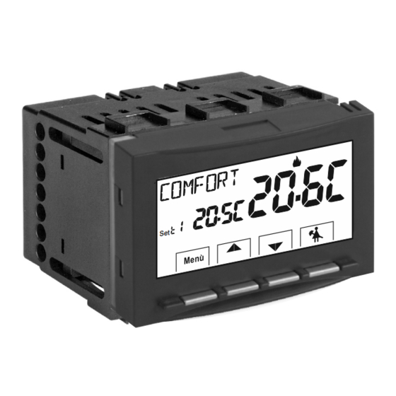
DIGITAL THERMOSTAT
MENU DRIVEN with BACKLIT DISPLAY
Flush-mounted installation 3 modules for civil series
PERRY ELECTRIC Srl
Via Milanese, 11
www.perry.it
22070 VENIANO (Como) ITALY
PE - DETIPE026EN 01/24
Mod. TE541
Series: V003
Power supply: 230V~
Winter
/ Summer
2
temperature levels
(t1 = Co fort, t2 = Economy)
+ OFF temperature level
=
I
nput for remote
external
contact
FULL instructions
for installation, settings and use
ENGLISH
Power supply
230V~
230V~
n
antifreeze
or thermal protection
www.perry.it
Advertisement
Table of Contents

Subscribe to Our Youtube Channel
Related Manuals for Perry Electric TE541


Summary of Contents for Perry Electric TE541
- Page 1 ENGLISH DIGITAL THERMOSTAT MENU DRIVEN with BACKLIT DISPLAY Flush-mounted installation 3 modules for civil series Mod. TE541 Power supply 230V~ 230V~ Series: V003 Power supply: 230V~ Winter / Summer temperature levels (t1 = Co fort, t2 = Economy) + OFF temperature level...
-
Page 2: Table Of Contents
CONTENTS pag. 3 DEVICE PRESENTATION 10. - Type of temperature adjustment mode pag. 17 pag. 3 WARNINGS 10. .1 - Selection of the temperature adjustment mode 1 - TECHNICAL DATA pag. 4 proportional differential ON/OFF) pag. 17 2 - FACTORY SETTINGS pag. - Page 3 PRESENTATION Dear Customer, thank you for choosing our product. The thermostat, suitable for all heating and/or cooling system, is fitted with a large and clear backlit display to keep all its functions under control in real time. The fundamental feature is its easy to use menu navigation, which makes it extremely user-friendly despite its comprehensive range of functions.
-
Page 4: Technical Data
TECHNICAL DATA Power supply: 230V~ +/- 10% 50Hz timed 6 secs. / always on / always off / brightness reduction after 6 sec. Display and key back-lighting: 1 B / Electronic Type of action, disconnection and device: voltage free relay with COM / NO / NC changeover contact, Type of output: max 5(3)A/250 V ~ Keeping memory setting during power failure:... -
Page 5: Factory Settings
2 -FACTORY SETTINGS The data entered in the thermostat called «FACTORY SETTINGS» refer to operation defined as «Standard». The following chapters describe all customisable functions, in order to satisfy any ambient comfort need. FACTORY SETTINGS TABLE (default) RESTORE «Installer RESET» DEFAULT PARAMETER RESTORE... - Page 6 3 - KEY FUNCTION LEGEND DISPLAY AND KEY BACK-LIGHTING Touching any key activates back-lighting, displaying the words selection and navigation press the desired key within 6 secs. to vary the settings (touching any key reactivates a 6 sec time- out). Note: setting the backlight always on (par.
-
Page 7: Display Features
4 - DISPLAY FEATURES Display Set temperature Currently active set temperature depending on the desired setting: Co fort or Economy ( saving ) or (antifreeze/ thermal protection Detected room temperature Note: further displays Remote thermostat control (connected to an external contact) are described in the specific operation Heating mode (... -
Page 8: Installation
5 - INSTALLATION 5.1 - DIMENSIONS 5.3 - INSTALLATION EXAMPLES Disconnect the 230V~ mains power supply Examples of installation in heating systems with a thermostat that controls: ) Wall mounted boiler ) Burner or Circulation pump or Motorized solenoid valve C Zone solenoid valve (example for floor system or other) -
Page 9: Electrical Connections
5 - INSTALLATION ELECTRICAL CONNECTIONS 5.4 - Examples of electrical connections Contact for remote Connection to a boiler ATTEN ION! Disconnect the 230V~ mains voltage thermostat control and to a external contact 230V~ 50Hz power supply terminals Connect line voltage power supply to the terminals: n°... -
Page 10: Start The Thermostat
6 - START THE THERMOSTAT The first time mains voltage is engaged, the thermostat performs a lamp-test by switching on all display segments, displaying the installed software version for a few seconds. When this phase is over, the thermostat displays the normal operation screen. Normal operation The thermostat is operational, it shows on the display: Winter mode (heating) - Page 11 7 - USE OF THE THERMOSTAT 7.2 - SELECTING AND SETTING THE DESIRED TEMPERATURE LEVEL: t1 (Comfort), t2 (Economy), OFF (Antifreeze or Thermal protection) From normal operation of the device, pulse the Mode button, display the desired temperature level t1 or t2 or OFF , confirm this by pressing the OK button.
-
Page 12: Setting The Current Winter/Summer Season
7 - USE OF THE THERMOSTAT 7.3 - SETTING THE CURRENT WINTER/SUMMER SEASON (Quick Command) Example: With the device in normal operation, press and hold the button for at normal operation least 6 seconds. WINTER season The product will present the proposed season change so if for example (heating) the current season is Winter (heating), it will show the icon... -
Page 13: Structure Of Menus Available
8 - STRUCTURE OF MENUS AVAILABLE (configuration) WARNING: access to the Prog menu (configuration) is recommended for the qualified installer or experienced user since the modification of some settings might affect correct system operation. Access to the menu can be password-protected (see par. 10.11 ). The following menus are available sequentially: = Season WINTER (heating) - Page 14 ACCESS TO THE CONFIGURATION MENU With previously entered password Normal operation (see par. 10.11 ) Press and hold 1° 2° at least 6 sec. Enter with buttons each digit confirming with OK password entered (in the event of an error, briefly press the Mode button to return to the previous screen)
-
Page 15: Configuration Menu (Installer)
10 - CONFIGURATION MENU (Installer) Current season flashing 10.1 - SETTING WINTER or SUMMER MODE From normal thermostat operation, access the menus by pressing and holding the « Mode » key as explained in chapter 9. • Under item Set SEAS confirm with •Select with the keys the WINTER... - Page 16 10 - CONFIGURATION MENU (Installer) MAX AND MIN SET TEMPERATURE LOCK (Winter and Summer mode) 10.3 - In certain device installations (public buildings, hotels, etc.) it might be useful to limit the temp. lock Winter mode maximum and/or minimum temperature set set and confirm points.
-
Page 17: Selection Of The Temperature Adjustment Mode
10 - CONFIGURATION MENU (Installer) 10. - TYPE TEMPERATURE ADJUSTMENT METHODS thermal inertia over temperature The thermostat is factory set to work in MODULATING PROPORTIONALLY °C of the heating element (P OP) mode setting cycles from 7 to 20 minutes (default minutes). T SET This system maintains the desired temperature more stable, whilst increasing the user's comfort sensation and saving on energy consumption. -
Page 18: Setting Hysteresis For Thermal Differential On-Off
10 - CONFIGURATION MENU (Installer) 10 4 . .2 - SETTING PERIOD DURATION FOR MODULATING PROPORTIONAL IN TIME PrOP •Select the SEt rEG , menu screen , as described in paragraph 10.4.1. •Press the button to display the next menu SEt Per period duration). -
Page 19: Set Off, Anti-Freeze Protection (Winter) Or Thermal Protection (Summer)
10 - CONFIGURATION MENU (Installer) 10.5 - SET OFF, Anti-freeze protection (Winter) or Thermal protection (Summer) •From normal operation of the thermostat, access the menus by holding down the Mode button as described in Chap. 9, the SEt OFF screen appears, confirm with •Select the SET OFF... -
Page 20: Management Of External Contact For Remote
10 - CONFIGURATION MENU (Installer) EXTERNAL CONTACT for remote thermostat switching on/off 10. - MANAGEMENT OF The thermostat is equipped with an input (AUX) for an external contact, it will be possible to connect accessory equipment (e.g. time switch, switch, window contact, etc.) that can deactivate the thermostat remotely, whose control must necessarily be potential-free. - Page 21 10 - CONFIGURATION MENU (Installer) 10 6 . .1 - RESETTABLE COMMAND on N.O. external contact “Normally Open” Confirmed screen for the management of the resettable N.O. external contact with a command on the thermostat as per the procedure in paragraph 10.6, the following operation is obtained:: Thermostat operation e.g.
-
Page 22: Resettable Command On N.c. External Contact
10 - CONFIGURATION MENU (Installer) 10.6.2 - RESETTABLE COMMAND on N.C. external contact “Normally Closed” Confirmed screen for the management of the resettable N.C. external contact with a command on the thermostat as per the procedure in paragraph 10.6, the following operation is obtained: Do not enable the item prior to connecting a switch or other device that allows change of state from... -
Page 23: Command Not Resettable On N.c. External Contact
10 - CONFIGURATION MENU (Installer) 10.6.4 - COMMAND NOT RESETTABLE on N.C. external contact “Normally Closed” Confirmed screen for the management of the N.C. external contact as per the procedure in paragraph 10.6, the following operation is obtained: Do not enable the item prior to connecting a switch or other device that allows change of state from OFF mode to current operating mode and vice versa to terminals and (AUX). -
Page 24: Brightness Adjustment (Back-Light)
10 - CONFIGURATION MENU (Installer) 10.8 - BRIGHTNESS ADJUSTMENT (back-light) Example: 7 default value This setting is only accessible if the SEt Led parameter is not set to (backlight always off) see par. 10,7 •From normal operation of the thermostat, access the menus by holding down the Mode button as described in Chap. - Page 25 10 - CONFIGURATION MENU (Installer) 10. - RESTORE ( factory reset IMPORTANT! The RESTORE (Reset) operation is recommended for the installer or expert user. In fact, this operation deletes many previous settings and programs carried out also according to the type of system. •From normal operation of the thermostat, access the menus by holding down the Mode...
-
Page 26: Entering And Managing Password
10 - CONFIGURATION MENU (Installer) 10.1 - ENTERING AND MANAGING PASSWORDS TO ACCESS THE MENUS •From normal thermostat operation, access the menus by holding down the “Mode” key as described in Chap. 9. •When the SEt COdE screen is displayed, confirm with , the first dash flashes •... - Page 27 10 - CONFIGURATION MENU (Installer) 10.12 - KEYBOARD LOCK (menu displayed ONLY with password set) IMPORTANT: this SEt LOC menu will only be VISIBLE if a Password previously been set (see par. 10.11). This function serves to prevent unauthorised persons from modifying any thermostat settings.
-
Page 28: Possible Problems And Solutions
1 - POSSIBLE PROBLEMS AND SOLUTIONS PROBLEM CAUSE SOLUTION Checl that the switch or protection differ- No power supply ential isn't on OFF The thermostat display is OFF After you turn off the power supply of Electrical cables not properly 230V ~ check the power cables if tightened in the terminals tightened to the appropriate terminals on...
Need help?
Do you have a question about the TE541 and is the answer not in the manual?
Questions and answers