Advertisement
Quick Links
PERRY ELECTRIC Srl
Via Milanese, 11 - 22070 VENIANO (CO) ITALY
www.perry.it
RECESS ELECTRONIC THERMOSTAT
INSTALLATION EXAMPLES
h 1,5 m
Install the thermostat at a height of 1,5 m ÷ 1,7 m from the floor, far from heat
sources, air vents, doors or windows and anything else that could affect its operation.
A
B
D
D
N.B.: the examples contained in this documentation are in principle.
SAFETY PRECAUTIONS!
&
Read this manual carefully before using the product as it provides important guidelines regarding safety, installation
and use. The manual must be preserved with care for future reference.
Important: installation and electrical connections of devices and appliances must be carried out by skilled people
and in compliance with current regulations
Before starting any operations on the device, disconnect the 230V~ mains power supply
The thermostat is not intended for use by persons (including children) with reduced physical, sensory or mental capabilities,
or by those with a lack of experience and knowledge of the instructions, unless they are supervised or have received the
necessary instructions concerning use of the device by a person responsible for their safety.
Children should be supervised to ensure that they do not play with the device.
If necessary, gently clean the thermostat and the display using a soft, dry cloth.
The manufacturer reserves the right to introduce any technical and/or constructive changes deemed necessary, with no prior notice.
COMPATIBILITY TO THE MOST COMMON RESIDENTIAL SERIES PLATES
IMPORTANT: for the assembly procedure of the thermostat with the chosen
residential plate, follow instructions contained in the specific compatibility
sheet contained in the package.
Models with LCD DISPLAY,
differential ON/OFF intervention and luminous charge inserted signal
Ins allation
t
a n d u s e r
in tructions
s
0
0
C
Heating systems with a thermostat
that controls:
A)
Wall mounted boiler
B)
Burner
C)
Circulation pump
D)
Zone solenoid valve
Series MODULE - H 45 mm
TECHNICAL DATA
DATI TECNICI
Supply voltage:
Type of action, disconnect and device:
Type of output
:
Output connection (load):
Inputs for remote "Reduction" control:
Wire section at terminals:
Insulation type:
Protection degree:
Pollution:
Operating temperature limits:
Storage temperature limits:
Temperature adjustment range:
Antifreeze temperature:
Temperature display scale:
R
educt
ion temperature:
(remote control)
Precision of
temperature
reading
:
Room temperature indicator resolution:
t
Differential operation -
selectable:
ERP Energy classification:
Thermal gradient:
Reference standard for CE mark:
DIMENSIONS
66
ENGLISH
230 V~ 50 ÷ 60 Hz
1/ B / Electronic
relay with changeover contact
NO / COM / NC - voltage free
max 8(2)A / 250 V~
2 or 3 conductors
for potential-free contact
2
2
min. 0,75 mm ÷ max. 2,5 mm
Class II
I 30
P
Normal
0 °C ÷ +50 °C
-10 °C ÷ +65 °C
+5 °C ÷ +30 °C (limitable)
+5 °C fixed
- 5 °C ÷ +39 °C
- 4 °C from the set temperature
("Winter" operation)
+4 °C from the set temperature
("
Summer
" operation)
± 0,5 °C
0,1 °C
0,3 °C - 0,5 °C - 0,7 °C - 0,9 °C
ErP: Class I; 1% Reg. EU 811/2013
1 °K/15 min
LVD
EN60730-2-9
EMC
EN60730-2-9
40
9
Advertisement

Related Manuals for Perry Electric MODULE Series


Summary of Contents for Perry Electric MODULE Series
- Page 1 ENGLISH PERRY ELECTRIC Srl Via Milanese, 11 - 22070 VENIANO (CO) ITALY www.perry.it RECESS ELECTRONIC THERMOSTAT Series MODULE - H 45 mm Models with LCD DISPLAY, differential ON/OFF intervention and luminous charge inserted signal TECHNICAL DATA Ins allation DATI TECNICI Supply voltage: 230 V~ 50 ÷...
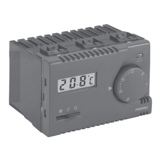
- Page 2 SIGNALS AND CONTROLS Load status LED (alight LED = load inserted) Temperature display - Display of room temperature - Display of temperature being set Temperature setting knob The display normally shows the detected room temperature. When setting the temperature with the knob, the display shows the temperature being set. A few seconds after the operation, the display goes back to the room temperature.
- Page 3 3 - LIMITATION OF THE MAXIMUM ROOM TEMPERATURE It is possible to preset from 16 °C to 24 °C, with 2 °C step, the maximum adjustable Range disc seat temperature value. Holes N.B.: the thermostat is supplied with the "range disc" preinstalled with pin in the neutral hole (no temperature limitation).
- Page 4 For more detailed information about recycling of this product, please contact your local city office, your house hold waste disposal service or the shop where you purchased the product. Perry Electric S.r.l. Via Milanese, 11 - 22070 Veniano (Co) - Italy...
Need help?
Do you have a question about the MODULE Series and is the answer not in the manual?
Questions and answers