
Subscribe to Our Youtube Channel
Related Manuals for CyberPower BPE36V60ART2U


Summary of Contents for CyberPower BPE36V60ART2U
- Page 1 User’s Manual EXTENDED BATTERY MODULE (EBM) BPE36V60ART2U BPE72V60ART2U Cyber Power Systems Inc. www.cyberpower.com K01-0000516-01...
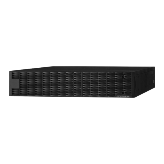
- Page 2 OVERVIEW The CyberPower Battery packs (BPE36V60ART2U / BPE72V60ART2U) support 50A polarized plugs, and are designed for variety of CyberPower UPS systems. When combining with the UPS, the Battery pack provides extended runtime with a 36VDC/72VDC external connection. Additional parallel-connected Battery packs provide the UPS for a longer extended runtime operation.
-
Page 3: Safety Precautions
Tighten the front rail screws on the rack. Step 2: Rackmount ears & hanging brackets installation Attach two rackmount ears to the EBM using the provided M5X7L*8pcs screws and tighten two hanging brackets with the M5X6L*6pcs screws. Copyright © 2023 CyberPower Systems, Inc. -
Page 4: Hardware Installation
Slide the hanging brackets on the EBM into the rails mounted in the rack with the front of the unit facing toward you. Secure the EBM to your rack with four M5X8L screws at the front of the rack. (Located in position 2 & position 5) Copyright © 2023 CyberPower Systems, Inc. -
Page 5: Vertical/Tower Installation
HARDWARE INSTALLATION VERTICAL/TOWER INSTALLATION Step 1: Adhere the rubber feet on the bottom side of base stands Step 3: Rotate the Multifunction LCD Module Adhere the protective rubber feet on the bottom side of base stands Unscrew the upper panel of the UPS. Separate the upper panel from the (rackmount ears) UPS system and EBM. -
Page 6: Basic Operation
Step 3: Rotate the battery cable retention bracket and tighten the two screws to fix battery cable. Step 4: Use a power cord to plug AC input inlet of the battery pack into a wall receptacle. Copyright © 2023 CyberPower Systems, Inc. - Page 7 Step 4: Rotate the battery cable retention bracket and tighten the two screws to fix battery cable. Step 5: Use a power cord to plug AC input inlet of the 2 battery pack into AC output outlet of the 1 Battery pack. Copyright © 2023 CyberPower Systems, Inc.
- Page 8 You may be prompted to save the selection, if so press the “ENTER” button to save the setting. Press the “ESC” button to cancel or return to the previous LCD menu. Configure Submenu Available Settings Default Settings EBP Number = [0] [1] [2] [3] [4] [5] [6] [7] [8] [9] [10] Copyright © 2023 CyberPower Systems, Inc.
-
Page 9: Maintenance
MAINTENANCE CAUTION! To avoid electric shock, turn off and unplug the EBM from Storage the wall receptacle before servicing the battery. To store your extended battery modules for a long period of time, turning CAUTION! Only use tools with insulated handles. Do not lay tools or DC breaker off, cover it and store with the batteries fully charged. -
Page 10: Technical Specifications
Replace Battery Contact technical support to replace the battery. insufficient runtime. Fault 1. Remove battery connector check Over Charge Battery is overcharged. charger voltage. Charger Failure Charger has failed. 2. Contact CyberPower for repair. Copyright © 2023 CyberPower Systems, Inc. - Page 11 For more information, please contact Location Company Address Tel/Fax email Europe Cyber Power Systems B.V. Flight Forum 3545, 5657DW Tel: +31 40 eu.service@cyberpower.com Northern Eindhoven, The Netherlands 2348170 Ireland Fax: +31 40 2340314 Austria Cyber Power Systems Edisonstrasse 16, 85716 Telefon: +49 89 de.service@cyberpower.com...
Need help?
Do you have a question about the BPE36V60ART2U and is the answer not in the manual?
Questions and answers