
Subscribe to Our Youtube Channel
Related Manuals for Flexit Muto 100


Summary of Contents for Flexit Muto 100
- Page 1 120245EN-01 2022-06 Muto 100, 160 ART.NR. 120200, 120201 ASSEMBLY AND OPERATION INSTRUCTIONS Single-room ventilatior...
-
Page 2: Table Of Contents
Description and use ................3 Compliance .................... 3 Safety ....................... 4 Structure and equipment ..............5 Single Room Ventilator Muto 100 installation ....... 6 Single room ventilator Muto 160 installation ......11 Use ......................18 Parameters programming sequences .......... 22 ................27 Technical data ..................30... -
Page 3: Description And Use
WiFi module for synchronisation with several units. The unit can be wall-mounted in perimeter walls with a 255 mm minumum tickness for “Single room ventilator Muto 100” and 270 mm minimum thickness for “Single room ventilator Muto 160”. The unit is available in two versions: •... -
Page 4: Safety
• If the appliance does not function correctly or develops a fault, contact a professional or the point of sale without delay. Ensure that only genuine original FLEXIT spares are used for any repairs. •... -
Page 5: Structure And Equipment
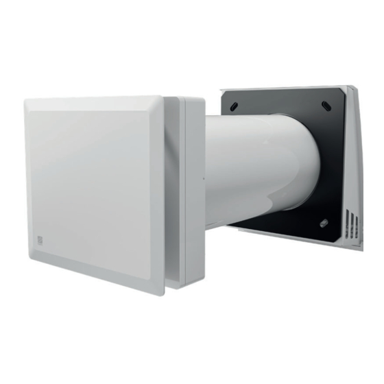
- Body with pre-assembled plug-in terminal block, frontal grille and aesthetic panel in - Motor holder and push-button panel in ABS material. - 5-speed reversible EC fan. - Integrated electronic board. • • • • Single room ventilator Muto 100 • • • Single room ventilator Muto 160 • • MUTO 100... -
Page 6: Single Room Ventilator Muto 100 Installation
PVC installation pipe and cut the pipe according to the wall thickness. It is mandatory to install “Single Room Ventilator Muto 100” within a perimeter wall with a 255 mm minumum thickness. ≥255 mm for MUTO 100 2°÷3°... - Page 7 15 mm...
- Page 9 Drill the two holes for the power cables and PCB signal cables inside the dotted area.
- Page 10 11 11 LOW VOLTAGE Remote Unit Sync Bus MAINS TERMINAL BLOCK 220-240V~50-60Hz MAIN BIPOLAR SWITCH WiFi Mesh Network UNIT #1 UNIT #2 REMOTE REMOTE CONTROL CONTROL L, N L, N 220-240V~50-60Hz 220-240V~50-60Hz...
-
Page 11: Single Room Ventilator Muto 160 Installation
Single room ventilator Muto 160 installation Fig 18 ÷ 35. NOTE: Before proceeding with the installation, remove the internal protective packaging in the appliance. NOTE: Before carrying out installation, remove the spacers inside the PVC installation pipe and cut the pipe according to the wall thickness. It is mandatory to install “Single room ventilator Muto 160”... - Page 12 0 mm 15 mm...
- Page 15 Drill the two holes for the power cables and PCB signal cables inside the dotted area. LOW VOLTAGE Remote dry contact TERMINAL BLOCK / MAINS 220-240V~50-60Hz MAIN BIPOLAR SWITCH / WiFi Mesh UNIT #1 UNIT #2 L, N L, N REMOTE CONTROL REMOTE CONTROL 220-240V~50-60Hz...
- Page 16 INSERTING METALLIC MESH FILTER “Single room ventilator Muto160” - INSERTING THE EXTERNAL FILTER 180°...
-
Page 18: Use
To use the appliance, make sure the lever of the closing disk is in the open positiion, by rotating the lever to position 2. Fig. 36A: WARNING: The control panel is accessible by inserting the hand in the space between the cover and... - Page 19 LED 5 / Boost LED 4 / High Performance ESTRAZIONE/AUTO COMFORT LED 3 / Performance IMMISSIONE/AUTO HR% LED 2 / Quiet RECUPERO/AUTO NIGHT LED 1 / Night PULSANTE PULSANTE PULSANTE FUNZIONE MODALITÀ VELOCITÀ value. The white LEDs from 1 to 5 will light up to indicate the speed from 1 to 5. The respective LEDs will light up steadily: •...
- Page 20 deactivate the stand-by mode. To activate or deactivate the stand-by mode: If the unit is switched on and the FUNCTION button, the appliance starts at the speed and mode previously set. The available functions are: • Auto night The ambient light sensor detects the presence or absence of ambient light and, depending on whether the measurement is higher or lower than the threshold value set via SW Therefore, at night when the presence of daylight is not detected, the appliance switches to minimum speed preventing the switch to a speed higher than the minimum one.
- Page 21 1. press the FUNCTION button for more than 2 seconds. 2. press the SPEED button to select one of the three LED 5 LED 4 function to be disabled. 3. press the MODE button to disable the function. 4. to SAVE the settings, press the FUNCTION button EXTRACTION /AUTO COMFORT LED 3 for more than 2 seconds.
-
Page 22: Parameters Programming Sequences
Parameters programming sequences To entry in programming mode: • • • Press the buttons in the following sequence: Speed - Speed - Mode - Function - Function – Mode. To set the relative humidity threshold: • Press the SPEED button. •... - Page 23 NOTE: units, it is necessary to set the type of unit • Press simultaneously the Speed - Mode - Function buttons. • Press in sequence the following buttons: Mode - Mode - Speed - Speed - Function - Function. • Press the Mode button within 20 sec. •...
- Page 24 WiFi Mesh Network installation and will become unique for each particular network once installation is completed. NOTE: The machines are set as SLAVE by factory default. You must therefore set a unit as button. • Press the SPEED - MODE - FUNCTION buttons on the MASTER unit at the same time. •...
- Page 25 • Press the SPEED - MODE - FUNCTION buttons at the same time. • Press the MODE - SPEED - FUNCTION - MODE - SPEED- FUNCTION buttons in sequence. • Press the MODE button within 20 second • • If the MODE button is not pressed within 20 seconds, all speed LEDs 1 to 5 will light up for resetting the network SSID.
- Page 26 EXAMPLE 1 EXAMPLE 2 1’÷2’ 1’÷2’ RECOVERY MODE FLOOR 1 SSID = VOR_1 LED 5 / Boost LED 4 / High EVEN Performance EXTRAXTION /AUTO COMFORT LED 3 / Performance 1’÷2’ 1’÷2’ INTAKE /AUTO HR% LED 2 / Quiet RECOVERY/AUTO NIGHT LED 1 / Night FLOOR 2...
- Page 27 Both models are equipped with a remote control with LCD display. By default the recovery function, The remote control transmits its default state to the unit and consequently updates the state on point the remote control towards the unit and press a button on the remote control to activate the FUNCTION Default state LCD ICON...
- Page 28 • at any time to toggle LCD ICON > > > • Press TIMED BOOST button at any time to toggle TIMED BOOST function ON and OFF. > > icon OFF> ON >... > • Press “heat recovery button” > , EXTRACT icon VENTILATION MODE icon •...
- Page 29 • Press the “supply” button SUPPLY > , EXTRACTION icon and VENTILATION MODE icon • to select this mode. EXTRACTION > if EXTRACTION button is pushed, • Press VENTILATION MODE button to select this mode. VENTILATION MODE > if VENTILATION MODE button and EXTRACTION •...
-
Page 30: Technical Data
Technical data Single Room Ventilator Single Room Ventilator Model Muto 100 Muto 160 Night Performance Boost Night 36,6 36,5 41,2 38,4 Sound powerlevel Performance 53,1 48,1 Boost 66,8 Night Performance 46,5 Boost Night 23,7 Soundpressure level Performance 32,0 25,4 35,6... -
Page 31: Maintenance And Cleaning
Maintenance and cleaning Filters cleaning or removed. or removed. described in the section “parameters programming sequence”, before returning to the normal functioning of the unit. • Decrease in machine yield and worsening of the indoor climat. -
Page 33: Disposal
Disposal The crossed-out wheeled bin symbol on the appliance indicates that, at the end of its life, the product should not be discarded together with household waste but must be taken to a separate collection point for electrical and electronic equipment. This will avoid negative of the materials from which the product is made. - Page 36 Flexit AS, Televeien 15, N-1870 Ørje www.flexit.no...
Need help?
Do you have a question about the Muto 100 and is the answer not in the manual?
Questions and answers