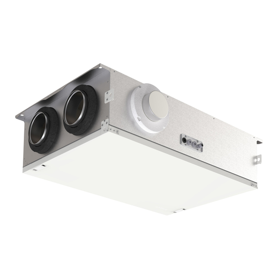
Flexit Nordic CL3 User Manual
Air handling unit
Hide thumbs
Also See for Nordic CL3:
- Installation instructions manual (36 pages) ,
- Manual (8 pages) ,
- Manual (8 pages)
Subscribe to Our Youtube Channel
Summary of Contents for Flexit Nordic CL3
- Page 1 117582-01 2019-09 Flexit Nordic CL3 ART.NO. 800200, 800201 USER MANUAL Air handling unit...
- Page 2 N O R D I C C L 3...
-
Page 3: Table Of Contents
Contents Automatic control......................6 Functional description of balanced ventilation .............7 2.1. Fans (M1, M2) ........................7 2.2. Filters (FI1, FI2) ........................7 2.3. Rotor (HR-R) .......................... 7 2.4. Heating element (EB1) ......................7 2.5. Temperature sensors (B1, B4) ..................7 2.6. For use with dampers ......................7 2.6.1. - Page 4 N O R D I C C L 3 Symbols used These products bear a number of symbols used for labelling the actual product and in installation and user documentation. Supply air Extract air Extract air from kitchen DANGER: DANGER! DO NOT ELECTRICITY TOUCH Exhaust air...
- Page 5 SAFETY INSTRUCTIONS • To avoid the risk of fire, electric • This unit is only designed for shock or injury, read all the safety ventilation air in homes and instructions and warning texts commercial buildings. before using the unit. • To maintain a good indoor •...
-
Page 6: Automatic Control
For more information on the automatic control system, Alternative user interfaces: • Flexit GO app (standard) • CI 70 control panel (accessory) To control the ventilation unit via a smartphone/tablet, See manual (116081). -
Page 7: Functional Description Of Balanced Ventilation
2. Functional description of balanced ventilation 2.1. FANS (M1, M2) 2.6. FOR USE WITH DAMPERS The fans ensure that air enters and leaves the building. 2.6.1. Damper (DA1) They can be individually adjusted for optimal operation. There is a closing air damper in the exhaust air duct the control panel: Home, Away, High. -
Page 8: Operating The Door
N O R D I C C L 3 3. Operating the door 3.1. LOCK 1. Turn the screw in the lock 90°. 2. Flip up the lock handle 3. The lock handle needs to be lifted right up to release. -
Page 9: Cleaning And Maintenance
4. Cleaning and maintenance Before opening the door: Turn the To avoid mixing the fans up, it is heat off and allow the fans to run best to disconnect one fan at a for three minutes to remove hot time. air. - Page 10 N O R D I C C L 3 4. Undo the two screws securing the fan to the partition. 5. Turn the fan to the side so that the curved grid clears the hole. 6. Remove the fan.
- Page 11 4.2. CHANGING THE FILTERS • • indoor air quality it is important to change them when should face the door. they are dirty. the degree of contamination of the air where they are least once a year, preferably in the autumn (after the pollen season).
-
Page 12: Changing The Brush Strips
N O R D I C C L 3 4.3. CHANGING THE BRUSH STRIPS TIP: You need a T20 Proceed as follows: The brush strips become worn over time. If they do not lie tightly against the rotary exchanger, it may be the circuit board. - Page 13 6. Pull the rotor module out and position it with the brush strip facing up. example. There are total of eight brush strips on the rotor, four on each side. Use a broad screwdriver so you can get good pur- and continue to the other.
-
Page 14: Cleaning The Rotor
N O R D I C C L 3 4.4. CLEANING THE ROTOR Further cleaning is possible by removing the rotor, spray- ing it with a grease solvent and then blowing it clean from the opposite side. Distance approximately 60 mm and max. -
Page 15: Maintenance Table
5. Maintenance table Component Action Interval Filter Filters must be changed at least once a year. It is best to do this twice a year, before and after 6-12 months Fans The fan in a unit connected to a kitchen hood should be inspected once a year. 12 months 3 years The fans should be cleaned as needed. -
Page 16: Troubleshooting
N O R D I C C L 3 6. Troubleshooting Type of fault Remedial action Cold draughts Check what supply air temperature has been selected. See control panel. Check that the rotor rotates. Check that heating comes on. Fans not working Check that power is connected to the unit. Check that the overheating thermostat has not cut out. -
Page 17: Complaints
Our products have been tested in accordance with Filters are consumables. 2006/42/EC Machine Directive (Safety) Producer: FLEXIT AS, Televeien 15, 1870 Ørje, Norway Our products are subject to continuous development and we therefore reserve the right to make changes. Type:... - Page 18 N O R D I C C L 3...
- Page 19 N O R D I C C L 3...
- Page 20 Flexit AS, Televeien 15, 1870 Ørje, Norway www.flexit.no...


Need help?
Do you have a question about the Nordic CL3 and is the answer not in the manual?
Questions and answers