Table of Contents
Advertisement
Quick Links
Advertisement
Table of Contents

Related Manuals for Fimer UNO-DM-6.0-TL-PLUS-US-Q


Summary of Contents for Fimer UNO-DM-6.0-TL-PLUS-US-Q
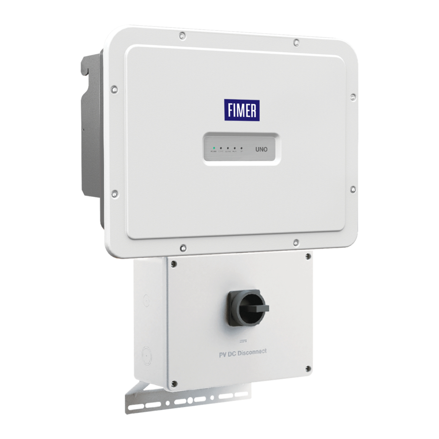
- Page 1 Product Manual UNO-DM-6.0-TL-PLUS-US-Q...
- Page 2 IMPORTANT SAFETY INSTRUCTIONS This manual contains important safety instructions that must be followed during the installation and maintenance of the equipment. SAVE THESE INSTRUCTIONS! Keep this document in a safe place near the inverter for easy access during installation, ope- ration and maintenance.
- Page 3 The products are designed to be connected to and to communicate information and data via a network interface. It is the user’s sole responsibility to provide and continuously ensure a secure connection between the product and the user’s network or any other network (as the case may be).
- Page 4 2 - Introduction and general information 3 - Characteristics 4 - Lifting and transport 5 - Installation 6 - Instruments 7 - Operation 8 - Maintenance 9 - Attachments FIMER-UNO-DM-6.0-TL-PLUS-US-QU Product manual EN-Rev B (M000051BG) EFFECTIVE 26/05/2021 © Copyright 2021 FIMER. All Rights Reserved.
-
Page 5: Table Of Contents
Table of Contents Table of Contents ............................5 Safety and accident prevention ......................9 Safety information and instructions ....................9 Symbols and signs ..........................10 Installation and maintenance safety ....................11 General safety information ....................11 Environmental conditions and risks ..................11 Electrical and thermal safety ....................12 Clothing and protection of personnel ..................13 Residual risks ............................14 Table of residual risks ......................14... - Page 6 Description of the inverter ........................35 Multiple-inverter system ......................35 Notes on system sizing ......................35 Inverter block diagram ......................35 PV plant block diagram ......................37 Operating diagram ........................37 Default functionality and components of the inverter ............38 Functionalities available with accessory board ..............39 Safety devices ............................41 Anti-Islanding ........................41 Photovoltaic panel ground fault ....................41 Arc Fault Detection (AFD) .....................41...
- Page 7 Communication and control signal connections to the accessory UNO-DM-COM KIT board ...66 Description of terminal blocks on the UNO-DM-COM KIT board ........67 Description of terminal blocks on the UNO-DM-PLUS-Ethernet COM KIT board ....68 Connection of the RS485 line .......................69 Remote control connection ....................71 Demand Responce Mode 0 (Request by AS/NZS 4777) .............71 Configurable Relay connection (ALARM / LOAD MANAGER) ...........72 Closing the front cover ........................73...
- Page 8 Storage and dismantling ........................136 Storage of an uninstalled inverter for long periods .............136 Storage of an installed inverter for long periods of non-use ..........136 Disposal..........................136 Attachments ............................ 137 Port and network services used by the inverter ................137 IP Network Services ......................137 Network Hosts ........................138 Inverter network configuration ....................138 Contact us ............................139...
-
Page 9: Safety And Accident Prevention
The operators must read and comply with the technical information and instruction provided in the manual and in the attached documentation. FIMER accepts no liability for failure to comply with the instructions for correct installation and cannot be held responsible for the upstream or downstream equipment. -
Page 10: Symbols And Signs
1 - Safety and accident prevention Symbols and signs In the manual and/or in some cases on the equipment, the danger are indicated with signs, labels, symbols or icons. Symbol Description General warning - Important safety information. Indicates a potentially hazardous situation which, if not avoided, could result in death or serious injury. -
Page 11: Installation And Maintenance Safety
1 - Safety and accident prevention Installation and maintenance safety General safety information Do not proceed with installation if the integrity of the equipment is compromised. Do not use the equipment if you find any operating anomalies. Avoid temporary repairs. All repairs should be carried out using only genuine spare parts, which must be installed in accordance with their intended use. -
Page 12: Electrical And Thermal Safety
Do not perform insulation or voltage withstand tests on the inverter. FIMER inverters must be earthed via the connection points marked with the protective earth symbol and using a cable with an appropriate conductor cross-section for the maximum ground fault current that the generating system might experience. -
Page 13: Clothing And Protection Of Personnel
1 - Safety and accident prevention Clothing and protection of personnel NFPA standards (which OSHA recommends and consults) require the equipment owner to field-label electrical equipment with labels contai- ning the available incident energy and required level of PPE, to protect both in-house and contract workers from electric shock and arc flash. -
Page 14: Residual Risks
1 - Safety and accident prevention Residual risks Despite the warnings and safety systems, there are still some residual risks that cannot be eliminated. These risks are listed in the following table with some suggestions to prevent them. Table of residual risks RISK ANALYSIS AND DESCRIPTION SUGGESTED REMEDY Noise pollution due to installation in unsuitable environments or where... -
Page 15: Introduction And General Information
FIMER declares that the equipment complies with the provisions of law currently in force in the country of installation and has issued the corresponding declaration of conformity. -
Page 16: Scope And Target Audience
List of appendix documents In addition to this user manual and maintenance you can consult (and download) the product documentation by visiting https://www.fimer. com. Part of the information given in this document is taken from the original supplier documents. -
Page 17: Application Area, General Conditions
2 - Introduction and general information Application area, general conditions FIMER shall not be liable for any damages whatsoever that may result from incorrect or careless operations. You may not use the equipment for a use that does not conform to that provided for in the field of use. -
Page 18: Characteristics
Characteristics General conditions A description of the equipment characteristics is provided to identify its main components and specify the technical terminology used in the ma- nual. This chapter contains information about the models, details of the equipment, characteristics and technical data, overall dimensions and equipment identification. -
Page 19: Models And Range Of Equipment
3 - Characteristics Models and range of equipment For each model, the following variant is available: - Model with “SB-RA” suffix (e.g. UNO-DM-6.0-TL-PLUS-US-SB-RA-QU). Meaning of the suffix SB-RA: S = DC disconnecting switch B = Wireless communication R = Rapid shutdown A = ARC fault device U = Unbalanced input channels The choice of the inverter model must be made by a qualified techni-... -
Page 20: Identification Of The Equipment And Manufacturer
(1) this device may not cause harmful interference, and (2) this device must accept any interference received, including interference that may cause undesidered operation. PN: PPPPPPPPPPP WO:XXXXXXXXXXXX SO: SXXXXXXXX SN:YYWWSSSSSS Fimer S.p.A. Via Tortona, 25 – I 20144 Milano (MI) - Page 21 The officially required information is located on the Regulatory label. The product label or the Wireless Identification label are accessory labels which shows the information necessary for the identification and characterisation of the inverter by FIMER. Note: The labels are NOT to be hidden by foreign objects and parts (rags, boxes, equipment,...
-
Page 22: Reference Number Index
3 - Characteristics Reference number index , Bracket , Wireless antenna , Accessory boards , Heat sink , DC Input terminal block , Protective Earth (PE) connection point , Inverter front cover , 3/4” DC conduit opening (1” drill Inverter , Wiring box front cover out marking) Wiring box... -
Page 23: Accessory Board Uno-Dm-Com Kit (Optional)
3 - Characteristics Accessory Board UNO-DM-COM KIT (optional) The inverter can be equipped with advanced accessory board PN: UNO-DM-COM Kit (ordered separately), adding: - An RS-485 serial interface - Configurable relay: - Remote switch-on/switch-off , UNO-DM-COM KIT , Inverter connector , RS485 Termination line jumper , DRM0 activation jumper , ALARM terminal block... -
Page 24: Technical Data
Auxiliary Output Isolated Auxiliary Power Supply 24Vdc, 0.4A max Embedded Communication Embedded Communication interface Wireless Embedded Communication Protocol ModBus TCP (SunSpec) Commissioning Tool Web User interface Plant Portfolio Manager, Plant Viewer, FIMER Ability Ener- Monitoring gy Viewer for solar plants... - Page 25 3 - Characteristics UNO-DM-6.0-PLUS-US-QU Optional board UNO-DM-COM Kit Optional Communication Interface RS485, Alarm/Load manager relay, Remote ON/OFF Optional Communication Protocol ModBus RTU (SunSpec), Aurora Protocol Optional board UNO-DM-PLUS-Ethernet COM Kit Optional Communication Interface Ethernet, RS485, Alarm/Load manager relay, Remote ON/OFF ModBus TCP (SunSpec),ModBus RTU (SunSpec), Aurora Optional Communication Protocol Protocol...
-
Page 26: Response To Abnormal Conditions
UNO-DM-COM kit UNO or UNO-DM-PLUS-Ethernet COM kit to a PC through a RS-485/USB adapter. Download the manual at www.fimer. com. An User ID and a password is required to unlock the “installer” fun- ctionalities of the software, contact FIMER solar inverter technical sup- port 1-877-261-1374. Fault currents and durations... -
Page 27: Grid Support Function
- Accessing the embedded Web User Interface. - Accessing to settings under the Service menu requires a time-limited password, which can be obtained by calling FIMER solar inverter techni- cal support at 1-877-261-1374. 1. Voltage ride-through This inverter provides parameters to respond to undervoltage and over- voltage events. - Page 28 This startup may occur on a daily basis or when the inverter restarts after an abnormal grid event has ended. Refer to the dedicated application note “Grid Support Function - Application Guideline” in the FIMER Solar website for more details about the grid support functions.
-
Page 29: Torques
3 - Characteristics Torques To maintain the NEMA 4X rating of the inverter and for correct installation, the following torques must be used: Front cover fastening screws 2.5Nm (1.8 ft-lb) Screw for 2.0Nm (1.5 ft-lb) Protective Earth (PE) connection point Outer dimensions The outer dimensions (inches) include the wall installation bracket. -
Page 30: Bracket Dimensions
3 - Characteristics Bracket dimensions The dimensions of the wall mounting bracket are expressed in inch. 0.24 0.31 0.31 0.91 0.91 3.41 3.42 1.25 1.25 3.41 3.42 17.98 SIDE VIEW SECTION VIEW (A-A) 1.98... -
Page 31: Efficiency Curves
3 - Characteristics Efficiency curves The equipment was designed considering current energy conservation standards, to avoid waste and unnecessary leakage. Graphs of the efficiency curves of all models of inverter described in this manual are shown below. The efficiency curves are linked to technical parameters that are continually being developed and improved and should therefore be considered approximate. -
Page 32: Power Limitation (Power Derating)
3 - Characteristics Power limitation (Power Derating) In order to allow inverter operation in safe thermal and electrical condi- tions, the unit automatically reduces the value of the power fed into the grid. Power limiting may occur due to: • Adverse environmental conditions (thermal derating) •... -
Page 33: Power Reduction Due To The Input Voltage
3 - Characteristics Power reduction due to the input voltage The graphs show the automatic reduction of supplied power when input voltage values are too high or too low. Pout Vs Vin (double input channel) Vin (Vdc) -
Page 34: Characteristics Of A Photovoltaic Generator
3 - Characteristics Characteristics of a photovoltaic generator A PV electric system consists of an assembly of photovoltaic modules that transform solar radiation into DC electrical energy and can be made up of: Strings: number of PV modules connected in series Array: group of strings connected in parallel Strings and arrays The string technology was developed to significantly reduce the instal-... -
Page 35: Description Of The Inverter
A setup program to help correctly size the photovoltaic system is available on the FIMER website (http://stringsizer.fimer.com). - Page 36 3 - Characteristics...
-
Page 37: Pv Plant Block Diagram
3 - Characteristics PV plant block diagram Grid Inverter AC breaker Grid distributor Disconnect Panels (Thermal-magnetic.) switch/es Operating diagram The plant diagram shows how the integrated WLAN board allows the inverter to connect to a LAN local network using a wireless connection. The WLAN board features an advanced integrated webserver that enables to establish a direct connection to a PC, smartphone or tablet, allowing for inverter setup and local monitoring of the inverter. -
Page 38: Default Functionality And Components Of The Inverter
All three product previously mensioned work toghether to allow solar power professional and site owners to collaboratively manage solar power plant. Please contact the FIMER tecnichal support for getting your own plant portfolio manager ac- count (mainly for installers and plant administrators). Please get your Plant Viewer and Plant Viewer for Mobile by accessing the website www.auroravision.net and click on “Register with... -
Page 39: Functionalities Available With Accessory Board
(UNO-DM- COM KIT or UNO-DM-PLUS-Ethernet COM KIT). Please contact the FIMER tecnichal support or get access to Sunspec alliance website for getting the Modbus register map supported by the inverter. - Configurable relay:... - Page 40 3 - Characteristics - Remote switch-on/switch-off This command can be used to switch off/switch on the inverter via an external (remote) command. This function must be enabled in the menu and when active, switch- ing on the inverter, besides being dictated by the presence of normal parameters which allow the inverter to be connected to the grid, also depends on the external command for switching on/off.
-
Page 41: Safety Devices
3 - Characteristics Safety devices Anti-Islanding In the event of a local utility company grid outage, or when the equipment is switched off for maintenance, the inverter must be physically discon- nected to ensure protection of people working on the grid, all in accor- dance with the relevant national standards and laws. -
Page 42: Other Safeguards
3 - Characteristics AC line, searching for any values that would indicate leakage of current to ground. Measurement of the ground leakage current is carried out simul- taneously by two independent and redundant processors. If either pro- cessor detects an unacceptable value as defined below, the inverter will immediately be disconnected from the grid, and it will lluminate the red LED GF indicator on the inverter front panel. -
Page 43: Lifting And Transport
Packaging must be disposed of in accordance with any local regulations. When the packaging is opened, confirm the inverter and components are not damaged and that nothing is missing. Immediately report any damage or missing parts to the delivery carrier and to FIMER Service. -
Page 44: Storage
4 - Lifting and transport Storage A maximum of 6 inverter may be stacked as shown in the side figure DO NOT stack with other equipment or products. Assembly brackets and/or accessory components are inside the packages. Weights Table: Weights Weight (Kg/lb) Lifting points (no.#) UNO-DM-6.0-PLUS-US-Q... -
Page 45: Packing List
4 - Lifting and transport Packing list All components required for installation (listed in the below table) are shipped with the inverter. Components Quantity Bracket for wall mounting M5x10 Wall bracket locking screw (to be used if required) M5 Wall bracket locking washer (to be used if required) (Spare part) T20 screw for front cover Cables for the configuration of the input channels in parallel sola... -
Page 46: Installation
Installation Installation warnings The inverter must be corrrectly installed, in a suitable location, to operate properly and safely. Installers must know and understand applicable NEC requirements and any local codes for photovoltaic systems. Installers must know and understand OSHA and other applicable safety requirements, inclu- ding lockout/tagout procedures. -
Page 47: Installation Site And Position
- If possible, install at eye level so that the LEDs can be easily seen - Install at a height that takes account of the weight of the equipment - All installations over 6500’ (2,000 meters) must be assessed by FIMER Technical Sales to determine the proper datasheet derating - Install vertically with a maximum inclination of 5°... -
Page 48: Installation Sites With High Humidity
5 - Installation - Position multiple inverters side by side, maintaining at least minimum clearances, measured from the outermost edge of the inverter. Keep in mind clearance and approach required for any removal or replacement! - Multiple inverters can also be placed in a staggered arrangement. Mi- nimum clearances for staggered arrangements include the width of in- verter plus additional allowances for inverters arranged above or below 6”... -
Page 49: Wireless Signal Environmental Checks
5 - Installation Wireless signal environmental checks The WLAN board of the inverter uses radio waves to transmit and re- ceive data, it is therefore important to assess this factor in order to have optimal installation. • Walls in reinforced cement and surfaces covered in metal (doors, shutters, etc.) can markedly reduce the reach of the device which even in optimal conditions, should be of approximately 50 metres in free space. - Page 50 5 - Installation Material of the structure: Concrete Distance X between the Inverter and the wireless Router: any distance Installation: to be evaluated. Assess the quality of the RF signal and the possibility of extending the signal with a repeater. Material of the structure: Metal or reinforced concrete Distance X between the Inverter and the...
-
Page 51: Recommendations For The Wireless Signal Power
5 - Installation Recommendations for the wireless signal power The radio signal level between the inverter and the wireless router can be improved in a number of ways: 1. Find a new position for the router considering the different types of materials which the radio signal will have to pass through: Material Relative signal reduction... -
Page 52: Wall Mounting
5 - Installation Wall mounting During installation do not place the inverter with the front covers facing the ground. 04 05 Install the inverter by following this procedure: Position bracket vertical support (pole, wall, frame, etc) and use it as drilling template. It is the installer’s responsibi- lity to choose an appropriate number and and distribution of... -
Page 53: Opening The Front Cover
5 - Installation Opening the front cover WARNING! ELECTRIC SHOCK HAZARD! Hazardous voltages may be present inside the inverter. The access to the internal zones of the inverter must be carried out after a minimum waiting time of 5 minutes since the inverter was disconnected from the grid and from the photovoltaic generator. -
Page 54: Installation Planning
UL489 or equivalent. front panel display. Use 90°C copper wire only. Refer to the instruction Maximum Current/Voltage UNO-DM-6.0-TL-PLUS-US-Q → 40A/600V for 208V and 240V grid manual for wiring instructions. ATTENTION Choice of grid output connection type (AC side) Ceci est un onduleur monophasé. -
Page 55: Sizing The Ground Cable(S)
5 - Installation Sizing the ground cable(s) FIMER inverters must be grounded at the protective earth (PE) connec- tion point terminal. Size the cable(s) in accordance with NEC and any local codes. The wire must be large enought to handle the maximum ground fault current that the PV system might experience. -
Page 56: Clamps Terminal Use
5 - Installation Clamps terminal use All power conductors will be inserter in spring clamp terminals. The figure shows an example of how to make the wires connection: - Insert a small flat screwdriver in the slot and lightly press the screwdriver from top to bottom;... -
Page 57: Preliminary Operations For Connection Of The Pv Generator
5 - Installation Preliminary operations for connection of the PV generator Independent or parallel input channels configuration The inverter is equipped with two input channels (thus benefiting from two trackers for MPPT maximum power point tracking) which work independen- tly of one another, which can be paralleled by leveraging a single MPPT. Strings of photovoltaic modules having the same type and number of panels in series must be connected to each single channel;... -
Page 58: Channel Configuration Examples
5 - Installation Channel configuration examples PV generator characteristics MPPT configu- Notes ration The photovoltaic generator consists A NECESSARY condition so that the two of strings having a different number MPPTs can be used in independent mode is for MPPT of modules in series from each other. -
Page 59: Independent Channel Configuration (Default Configuration)
5 - Installation Independent channel configuration (default configuration) This configuration is set at the factory and involves the use of the two input channels (MPPT) in an independent mode. This means that the jumpers (supplied) between the positive and negative poles of the two DC input channels must not be installed, and that the “independent”... -
Page 60: Checking The Correct Polarity Of The Strings
5 - Installation Checking the correct polarity of the strings Using a voltmeter, check that the voltage of each string has the correct polarity and falls within the input voltage limits of the inverter (see techni- cal data). Polarity inversion can cause serious damage. If the open circuit voltage of the string is near the maximum value ac- cepted by the inverter, consider that low ambient temperatures cause an increase in the string voltage (different according to the photovoltaic... -
Page 61: Electrical Connection To The Pv Field - Dc Side
Array equipment grounding must be installed per the requirements of the NEC and is the responsibility of the installer. A configuration program that can help to correctly size the photovoltaic system is available on at http://www.stringsizer.fimer.com. - Turn the DC switch OFF... - Page 62 5 - Installation are spring pressure type and accommodate a wire size range of 20-8 AWG. Connect the strings in either independent or parallel mode, following the appropriate set of instructions below: DC connection with INDEPENDENT MPPT configuration If two PV arrays with each be below the maximum input current rating of the inverter, they may be connected as “IND”...
-
Page 63: Grid Output Connection (Ac Side)
5 - Installation Grid output connection (AC side) CAUTION This is a single phase inverter. Use the wiring schemes shown on the Wire must be sized based on ampacity requirements of the NEC or other applicable prevail- table below when a different grid standard is used. Refer to the ing code. -
Page 64: Grid Standard Setting Of The Country
5 - Installation - Connect the main AC ground cable in the raceway to protective earth (PE) connection point If several inverters are installed to a three-phase AC GRID, always distribute the inverters between the phases in order to reduce power imbalance between the phases. Always refer to the local standards. -
Page 65: Rapid Shutdown (Rsd) Connection
5 - Installation Rapid Shutdown (RSD) connection The installer must use an external rapid shutdown device compliant with the 2014 NEC. Automatic shutdown occurs at the rooftop box when utility power is lost or when the PV system’s AC disconnect switch is opened. In jurisdictions requiring a dedicated activation switch, install an emergency stop button external to the inverter. -
Page 66: Communication And Control Signal Connections To The Accessory Uno-Dm-Com Kit Board
5 - Installation Communication and control signal connections to the accessory UNO-DM-COM KIT board To connect the signal cables to the UNO-DM-COM KIT or UNO-DM- PLUS-Ethernet COM KIT board is necessary to: - Remove both front covers (wiring box and inverter compartment - Insert the appropriate water-tight conduit connector on signal conduit opening and tighten to the chassis to maintain NEMA 4X compliance. -
Page 67: Description Of Terminal Blocks On The Uno-Dm-Com Kit Board
5 - Installation Description of terminal blocks on the UNO-DM-COM KIT board ALARM RS485 Description of multifunctional relay terminal block Terminal Terminal Description name number N.C. "Normally closed" terminal of multifunctional relay ALARM "Common" terminal of multifunctional relay N.O. "Normally open" terminal of multifunctional relay Description of communication and control signal terminal block Terminal Terminal... -
Page 68: Description Of Terminal Blocks On The Uno-Dm-Plus-Ethernet Com Kit Board
5 - Installation Description of terminal blocks on the UNO-DM-PLUS-Ethernet COM KIT board Description of multifunctional relay terminal block Terminal Terminal Description name number N.C. "Normally closed" terminal of multifunctional relay ALARM "Common" terminal of multifunctional relay N.O. "Normally open" terminal of multifunctional relay Description of communication and control signal terminal block Terminal Terminal... -
Page 69: Connection Of The Rs485 Line
5 - Installation Connection of the RS485 line On the inverter models which equip the UNO-DM-COM KIT or UNO- DM-PLUS-Ethernet COM KIT board it is possible to use the RS485 com- munication port for: Integrating the inverter with a third party monitoring and control systems;... - Page 70 5 - Installation The RS485 HALF-DUPLEX communica- tion line is made up of two transmission and reception cables (+T/R and –T/R) and a communication reference cable (RTN): all three cables must be connect- ed in daisy-chain configuration (it’s rec- ommended to make connection external to the inverter).
-
Page 71: Remote Control Connection
5 - Installation Remote control connection The connection and disconnection of the inverter to and from the grid can be controlled through an external control. The function must be enabled in the specific section of internal webserver (see the specific chapter). If the remote control function is disabled, the switching on of the inverter is dictated by the presence of the normal pa- rameters that allow the inverter to connect to the grid. -
Page 72: Configurable Relay Connection (Alarm / Load Manager)
5 - Installation Configurable Relay connection (ALARM / LOAD MANAGER) The UNO-DM-COM KIT or UNO-DM-PLUS-Ethernet COM KIT boards is equipped with a relay with configurable activation that allows connection of external devices which for example, signal malfunctions to manage loads with a specific configurable power input threshold, according to the mode selected in the specific section of internal webserver (see the specific chapter). -
Page 73: Closing The Front Cover
5 - Installation Closing the front cover At the end of the inverter connection and configuration stage and before proceeding with the commissioning, the inverter's covers wir- and the ing box covers must be closed. During the installation of the cover, the installation sequence must be respected as well as the tightening torque of the screws (set out in the paragraph on technical data) in order to maintain NEMA Type 4X enclosure integrity. -
Page 74: Instruments
The FIMER solar inverter help desk may be reached at 1-877-261-1374, 6am - 6pm (PST) Monday-Friday. excluding major holidays. Do not use the inverter or the PV plant if the operator: - is not trained or qualified to work on this PV plant;... -
Page 75: Description Led Panel
6 - Instruments Description LED Panel POWER COMM ALARM WLAN LEDs Solid when the inverter is working correctly. Flashes when checking the grid or if POWER Green there is insufficient sunlight. Operation status of wireless communication line: COMM Multi- - Blink Red: Communication error (no communication available) STATUS color - Green: Communication OK... -
Page 76: Operation
Operation Introduction and operation warnings Before commissioning the inverter, it is necessary to have a thorough knowledge of the Instruments chapter 6 and the functions thatis possible to enable in the commissioning phase. When the inverter is commissioned operates automatically without the aid of an operator;... -
Page 77: Monitoring And Data Transmission
• Data transmission on the dedicated RS-485 serial line. The data can be collected by a PC or a data logger equipped with an RS-485 port. Contact the FIMER support service with any queries about device compatibility. Measurement tolerance The data supplied by the inverter may differ from measurements taken by certified measuring instruments (e.g. -
Page 78: Commissioning (Via Internal Webserver)
7 - Operation Commissioning (Via internal Webserver) Do not place objects of any kind on the inverter during operation! Do not touch the heat sink while the inverter is operating! Some parts may be very hot and could cause burns. Before proceeding with commissioning, make sure you have carried out all the checks and verifications indicated in the section on preliminary checks. - Page 79 7 - Operation • When required digit the network password FIMERSOLAR After 24 hours wich the inverter is power-on, the access point default password “FIMERSO- LAR” will be disabled and any subsequent access to the internal webserver will be possible only using the PRODUCT KEY (printed on the “Wireless identification label”...
- Page 80 7 - Operation STEP 2 (Optional) - Residential wireless network connection. The inverter WLAN board can operate in two different operating modes: “Station Mode” or “Access Point Mode” (also known as “AP Mode”) • “AP mode”: Only local communication is enabled in this mode; In particular, the WLAN board acts like an «access point»...
- Page 81 7 - Operation The parameters relating to the home wireless network (set on the router) that must be known and set during this step are: - IP Settings: DHCP or Static. If you select the DHCP function (default setup) the rou- ter will automatically assign a dynamic IP address to the inverter whenever it tries to connect to the user network.
- Page 82 7 - Operation Once the inverter is connected to the domestic wireless network, a new message will confirm that the connection is acquired. The message provides the IP Address assigned by the home wireless network router to the inverter that can be used each time you want to access the internal webserver, with the inverter connected to the home wireless network.
- Page 83 7 - Operation STEP 3 - Date, Time and Time zone Set the Date, Time and Time zone (The inverter will propo- se these fields when available). When it’s not possible for the inverter to detect the time protocol, these fields have to be manually entered. Click on “Next”...
- Page 84 7 - Operation STEP 4 - Inverter country standard, Input configuration and Meter configuration - Country standard: selection of grid standard: Set the grid standard of the country in which the inverter is installed. From the moment that the grid standard is set, you have 24 hours to make any changes to the value, after which the “Country Select >...
- Page 85 Webserver (please see the beginning of this paragraph on how to access to the internal webserver). In addition it is possible to use the mobile App ‘FIMER ability Energy Viewer for solar plants’ and the FIMER Web portal Aurora Vision (please refer to product manual for fur-...
-
Page 86: Power, Alarm, Gfi Leds Behavior
7 - Operation Power, Alarm, GFI LEDs behavior The following table shows all the possible activation combinations of “Power” “Alarm” and “GFI” LEDs on the LED panel according to the operating status of the inverter. = LED On = LED flashing slow (2 seconds on / 2 seconds off) = LED flashing fast (0.2 seconds on / 0.2 seconds off) = LED off = Any one of the conditions described above... -
Page 87: Comm, Wlan Leds Behavior
7 - Operation Power: DC arc fault detected during operation Alarm: If a DC arc fault is detected during operation, the inverter disconnects from AC grid (the error GFI: code is readable through internal Webserver). Power: AFD board self test failure Alarm: Potential problem on the AFD board detected during self test phase GFI:... -
Page 88: Description Of The Internal Webserver
7 - Operation Description of the internal Webserver The UNO-DM-TL-PLUS inverters are equipped with an advanced in- tegrated webserver and user interface that allow a full access to all configuration and comissioning parameters from any electronic device (laptop, tablet and smartphone). The screenshots shown in this chapter are indicatives and it could be changed without any notification. - Page 89 7 - Operation Connection to the inverter in “AP Mode” If the inverter wasn’t connected to the domestic wireless network, follow this procedures: • Enable the wireless connection on the device which is being used for the board setup (tablet, smartphone or PC) and connect it to the Access Point created by the inverter system: the name of the wireless network created by the system that the connection should be established with, will be:...
- Page 90 7 - Operation Login page After you have connected the device to the inverter and you access to the login page, login with the username and password created during the commissioning phase. User and password are CASE SENSITIVE. If the Password is lost click on “Forgot your password?” to obtain the access to the webserver (and it will be possible to change the password) by entering the PRODUCT KEY (printed on the “Wireless identification label”...
-
Page 91: Webserver Menu Structure
7 - Operation webserver menu structure The following screenshots are related from a laptop visualization, may differ from smartphone or tablet visualization. The Webserver is divided in six main sections, available on the left side- bar: MAIN: Main section of webserver dedicated to viewing the summary informations related the status and the production informations of the inverter and photovoltaic plant. -
Page 92: Main Section
7 - Operation MAIN section In the MAIN section it’s possible to access the following sub-menus: • Dashboard • Status Summary Dashboard In the Dashboard sub-menu you can view the main informations relat- ed the status and the production informations of the inverter and photo- voltaic plant and alarm/warning active events. -
Page 93: Setting Section
2. REACT-MTR-1PH (single-phase) 3. FIMER 1PH (single-phase) 4. FIMER 3PH (three-phase) If a 3PH energy meter (FIMER B23, B24) is used in the system as single-phase inverter, it will be necessary to select FIMER 3PH and the phase to which the inverter is connected. - Page 94 7 - Operation ENERGY POLICY: set the way in which you want to manage the energy produced by the PV plant, choosing from the following: Management Description mode The system automatically manages power flows in or- der to maximise self-consumption. All unused power Self from domestic loads will feed into the grid.
- Page 95 We advise changing the activation voltage only if really necessary and to set it to the correct value: the photovoltaic generator sizing tool available on the FIMER website will indicate whether Vstart needs changing and what value to set it to.
- Page 96 7 - Operation 5.4 Multiple Max Scan Enable This settings allows you to Enables/disables the scan for identifying the maximum power point of the system. 6.4 Multiple Max Scan Period This settings allows you to set the time between scans. Remember that the shorter the scan interval the greater the loss of production, due to the fact that energy is transferred to the grid during the scan but not at the maximum power point.
-
Page 97: Inverter Log Section
7 - Operation Inverter Log Section In the Inverter Log Section it’s possible to view the Alarm and Warning events list that it can be custom filtered by type or by entering a match- ing word. Clicking on any event to view his details. -
Page 98: User Section
To access on the internal webserver with the “Admin Plus” user privi- leges it’s required to enter a security token that it can be obtained by registering on the website https://registration.solar.fimer.com. Refer to the dedicated section on this topic in the manual. -
Page 99: Connectivity Section
400/4800/9600/19200/34800/57600/115200). • RS485 Protocol Type: It allows you to set the type of protocol to be used for the RS485 line. - “Protocol Aurora Server”: it’s the proprietary FIMER serial protocol usually used for back-compatibility or by service personnell. - “Modbus Sunspec Server”: General purpose commu- nication protocol to be selected to enable monitoring and control. - Page 100 7 - Operation WLAN In the WLAN sub-menu it’s possible to view operation status and the information about the WLAN board for both of wireless channel and to switch between the two operation mode (“Station Mode” or “AP Mode”). Wireless channel 1 is always active and it’s dedicated to operate in Access Point mode only.
- Page 101 7 - Operation Once the inverter is connected to the domestic wireless network, a new message will confirm that the connection is acquired. The message provides the IP Address assigned by the home wireless network router to the inverter that can be used each time you want to access the internal webserver, with the inverter connected to the home wireless network.
- Page 102 Complete the additional fields at the bottom of the screen (all the fields are mandatory with the exception of the secondary DNS server). Debug Settings In the Debug Settings sub-menu it’s possible to enable or disable the Debugging access for FIMER Service purposes.
-
Page 103: Service Tools Section
7 - Operation SERVICE TOOLS section In the TOOLS section it’s possible to access the following sub-menus: • Country Standard • Firmware Update • Date/Time • Reset AFD Country Standard By accessing to the Country Standard sub-menu you can modify the grid standard within 24 hours while the inverter is operating. - Page 104 The latest firmware version is available from the download area of the website www.fimer.com or from https://registration.solar.fimer.com Click on “FW SELECT” and select the firmware package previously downloaded.
- Page 105 7 - Operation Date and Time In the Date and Time sub-menu it’s possible to set the date, time and time zone. The inverter will propose these fields when the time protocol is availa- ble). When it’s not possible for the inverter to detect the time protocol, these fields have to be manually entered.
-
Page 106: Information
7 - Operation Information In the INFORMATION Section it’s possible to view the general informa- tions about the embedded Web User Interface. it’s possible to access the following sub-menus: • Product Info • Privacy Policy • Provider Information/Impressum • Acknowledgments •... -
Page 107: Maintenance
Maintenance General conditions Routine and periodic maintenance operations must only be carried out by specialized staff with knowledge of how to perform these tasks. Some inverter parts may be subject to voltages that could be hazardous for the operator. Befo- re performing any work on the inverter, refer to “Inverter total de-energization and safe access”... -
Page 108: Inverter Total De-Energization And Safe Access
8 - Maintenance Inverter total de-energization and safe access The purpose of this chapter is to provide instructions for de-energize the UNO-DM-PLUS models in order to allow access to active parts inside the inverter. The procedure describes the steps to perform a total isolation and thus includes operations on devices that are located outside the in- verter. -
Page 109: Clothing And Protection Of Personnel
8 - Maintenance Clothing and protection of personnel The following Personal Protective Equipment (PPE) are required to per- form any intervention on the inverter: • Dielectric helmet EN397 – EN50365 (1000Vac-1500Vdc) with visor EN166 grade 8. • Insulating composite gloves class 0 EN60903 (1000Vac-1500Vdc) resistant to electric arc class 2 (7kA) EN61482-1-2 in combination with protective overglove in leather EN420 –... -
Page 110: Inverter Total De-Energization And Safe Access Procedure
8 - Maintenance Inverter total de-energization and safe access procedure... - Page 111 8 - Maintenance When the device has just been switched off, it may have hot parts as a result of overheating of the heated surfaces (e.g.: transformers, accumulators, coils, etc.) so be careful where you touch. Some inverter parts may be subject to voltages that could be hazardous for the operator. Be- fore performing any work on the inverter, follow this procedure for safely isolate the inverter.
- Page 112 8 - Maintenance 4. Operations on External AC switches The diagram below represents a possible arrangement of the PV plant. Depending on the design choices made by the developer of the plant some of the devices could not be present. Identify the external AC switch(es) in the plant with the support of the plant manager.
- Page 113 8 - Maintenance 5. Operations on External DC switches (if present) Note: In case of absence of External DC disconnect device skip this step. The diagram below represents a possible arrangement of the PV plant. Depending on the design choices made by the developer of the plant some of the devices could not be present.
- Page 114 8 - Maintenance 6. Operations on Internal DC disconnect switch • Open the internal DC switch (blue in the below picture). INVERTER 1 (Unit under service) OPEN LOTO LV/MW Internal DC Transformer Switch OPEN+LOTO OPEN+LOTO External LV External Main LV External DC MW Switch AC Switch...
- Page 115 8 - Maintenance The below picture represents the expected status of the switches in the plant after the switching operations have been completed. INVERTER 1 (Unit under service) OPEN LOTO LV/MW Transformer Internal DC Switch OPEN+LOTO OPEN+LOTO External DC External LV External Main LV MW Switch Switch...
- Page 116 8 - Maintenance 7. Remove the DC cables • Using the current clamp check the absence of current on DC side, measurement each positive and negative DC input string cables (check the correct setting of the current sensor). • Remove DC cables from the DC Input terminal block To avoid mechanical interferences, use a cable tie to collect the disconnected cables.
- Page 117 8 - Maintenance 13. Check list to be filled prior the access to the inverter • Purpose of the checklist is to verify that all the operations mentioned in the procedure have been carried out. The checklist below must be attached to the intervention report. CHECK STATUS √...
-
Page 118: Routine Maintenance
To preserve long term proper operation of the inverter, you are advised to perform the routine maintenance operations listed in this chapter. Maintenance operations shall be performed only by qualified personnel or FIMER personnel (under a servicing contract). The maintenance schedule may vary depending on the envi- ronmental conditions of the installation. -
Page 119: Troubleshooting
8 - Maintenance Troubleshooting Operations on the inverter to identify and address any faults may only be performed by the installer or by qualified personnel. Internal Web user interface and wireless communication troubleshooting The following table gives a list of main and most common errors or problems relating to the wireless communication between inverter and user devices. - Page 120 8 - Maintenance Problem Possible causes Solution The MAC address used to register the Make sure that the MAC address registered on the Aurora Vi- inverter on the Aurora Vision platform is ® sion platform is actually the one associated with the inverter. If ®...
-
Page 121: Alarm Messages Of The Inverter
8 - Maintenance Alarm Messages of the Inverter In order to understand and resolve warning (Wxxx) or error (Exxx) sig- nals that appear in the Alarm section of the internal web user interface, follow the table given in the following paragraph. The equipment can notify errors/warnings in the Alarm section of the inter- nal web user interface only if the input voltage is greater than the Vdcmin voltage (POWER Led flashing or lit;... - Page 122 8 - Maintenance - Error code - Error message Name of Alarm and Cause Solution - Signal • Check the grid voltage on the inverter. - Should it be absent, check for absence of grid voltage on the supply point. - If, on the other hand, the voltage tends to rise (when the in- verter is connected) there is high line or grid impedance.
- Page 123 8 - Maintenance - Error code - Error message Name of Alarm and Cause Solution - Signal • Raise the value of the activation voltage (Vstart) if the prob- lem at the time of the inverter’s grid connection (Using the for- mulas 0,7*Vmp,stc or 0,6*Voc,stc).
- Page 124 8 - Maintenance - Error code - Error message Name of Alarm and Cause Solution - Signal Resetting of the Latch alarm conditions: • The reset of the Latch alarm conditions is done directly by - W027 * Manual reset of the Latch alarm conditions; this opera- the customer/installer and is not an error.
- Page 125 8 - Maintenance - Error code - Error message Name of Alarm and Cause Solution - Signal Once the error occurs, the inverter tries to return to normal op- eration. - Should the error occur sporadically, it may be caused by a - E007 Saturation recorded on the IGBT components: brusque transition of the grid voltage or of the input voltage, but...
- Page 126 8 - Maintenance - Error code - Error message Name of Alarm and Cause Solution - Signal Failure of test on sensor to measure the leakage current (DC side): Before connecting to the grid the inverter runs a au- • Error inside the inverter and cannot be checked externally. totest regarding the sensor for the leakage current.
- Page 127 8 - Maintenance - Error code - Error message Name of Alarm and Cause Solution - Signal Grid frequency outside of range: - E028 Error in the internal measurement of grid frequency • Error inside the inverter and cannot be checked externally. - Error Meas F (set by law) in order to have a redundant measurement - If the problem persists (once the inverter has been switched...
-
Page 128: Power Limitation Messages
8 - Maintenance - Error code - Error message Name of Alarm and Cause Solution - Signal E055 • Error inside the inverter and cannot be checked externally. Arc Fault board parameter reading error: - AFDD wrong conf. - If the problem persists (once the inverter has been switched Error in the parameter reading by the system. -
Page 129: Dismantling The Inverter
8 - Maintenance Dismantling the inverter Before attempting any work on the inverter, wait for stored energy to be discharged and for parts to cool. • Open the external DC and AC discon- nects switches. • Disconnect any power supplies that may be connected to the UNO- DM-COM KIT or UNO-DM-PLUS- ETHERNET COM KIT. -
Page 130: Calculation Of Second-Level Password (Service Menu, Admin Plus)
In order to obtain the second-level password needed to access the inver- ter's display service menu or to obtain the “Admin Plus” privileges in the internal webserver, contact FIMER Technical Sales (1-877-261-1374) keeping the following information on hand: - S/N - Serial number of the inverter. This information can be found on the product label giving the identity details of the inverter. -
Page 131: Replacement Of The Memory Board
8 - Maintenance Replacement of the MEMORY board Some inverter parts may be subject to voltages that could be hazardous for the operator. Before performing any work on the inverter, refer to “Inverter total de-energization and safe access” chapter on this manual to know all the necessary step to safely operate on the inverter. Replacing the MEMORY board may be necessary in the following cir- cumstances: Inverter log Statistic (e.g. -
Page 132: Replacement Of The Buffer Battery
8 - Maintenance Replacement of the buffer battery Some inverter parts may be subject to voltages that could be hazardous for the operator. Before performing any work on the inverter, refer to “Inverter total de-energization and safe access” chapter on this manual to know all the necessary step to safely operate on the inverter. Replacing the buffer battery may be necessary in the following cir- cumstances: 1. -
Page 133: Verification Of Ground Leakage
8 - Maintenance Verification of ground leakage In the presence of anomalies or report of ground fault (where provided), there may be a ground leakage from the PV generator (DC side). To check this, measure the voltage between the positive pole and ground and between the negative pole (of the PV generator) and ground using a voltmeter whose input accepts a voltage of at least 1000 Volts. -
Page 134: Behavior Of A System With Leakage
8 - Maintenance Behavior of a system with leakage If the voltage measured between one of the two poles and ground does not tend to 0V and stabilizes on a value, there is a ground leakage from the PV generator. Example: When the measurement is made between positive pole and ground, a voltage of 200V is measured. -
Page 135: Measuring The Insulation Resistance Of The Pv Generator
8 - Maintenance Measuring the insulation resistance of the PV generator. To measure the insulation resistance of the PV generator compared to ground , the two poles of the PV generator must be short-circuited (using a suitably sized selector). Once the short-circuit has been made, measure the insulation resistance (Riso) using a megohmmeter positioned between the two shorted poles and ground (of the inverter). -
Page 136: Storage And Dismantling
Disposal FIMER CANNOT be held responsible for disposal of the equipment (ca- bles, batteries, etc.). The customer must dispose of these items, some of which be harmful to the environment, in accordance with the local... -
Page 137: Attachments
TCP connections. Direction Service/Port Protocol Description For local debugging by FIMER service personnel, the inver- ssh/22 ter utilizes encrypted SSH. To allow service personnel local access to the inverter. The inverter must be able to resolve domain names, to en-... -
Page 138: Network Hosts
Network Hosts The inverter will connect to the following hosts. Some servers owned by FIMER, and others are customer or ISP servers. Servers listed as ow- ned by “Customer IT/ISP” must be configured in the inverter using either DHCP or as static network information. -
Page 139: Contact Us
With regard to purchase orders, the agreed Any reproduction, disclosure to third parties or representative or visit: particulars shall prevail. FIMER does not accept utilization of its contents – in whole or in parts – is any responsibility whatsoever for potential errors or forbidden without prior written consent of FIMER.
Need help?
Do you have a question about the UNO-DM-6.0-TL-PLUS-US-Q and is the answer not in the manual?
Questions and answers