Table of Contents
Advertisement
Quick Links
Advertisement
Table of Contents

Related Manuals for AlphaESS STORION-H30-O


Summary of Contents for AlphaESS STORION-H30-O
- Page 1 INSTALLATION MANUAL OF ENERGY STORAGE SYSTEM STORION-H30-O...
-
Page 2: Copyright Statement
COPYRIGHT STATEMENT Copyright Statement The copyright of this manual is owned by Alpha ESS Co., Ltd. and all rights reserved. Without written permission of the Company, no unit or individual is allowed to extract or copy any part or the entirety of the content within this document. Furthermore, it is strictly prohibited to spread, modify, or copy the content in any form. -
Page 3: Notice
Please note that some of the products, services or features de- scribed in this document may not be included in your purchase or use. AlphaESS does not make any representations or warranties of any kind, whether express or implied, regarding the contents of this document, except as otherwise agreed in the contract. -
Page 4: Preface
PREFACE Preface After years of dedicated research and development by AlphaESS, the STORION-H30- O lithium-ion battery outdoor energy storage system has been successfully applied to many sites. This high-tech product with excellent quality and stable performance, is widely used in electric power supply industry today. -
Page 5: Symbol Convention
SYMBOL CONVENTION Symbol Convention The following symbols may appear in this manual, and their meanings are as follows. Symbol Description Indicates a potential risk that could lead to system failure or fault alarm if not avoided. Indicates a medium level of risk that could lead to system damage or injury if not avoided. -
Page 6: Terminology
TERMINOLOGY Terminology 1. Battery Management System (BMS) It is used to monitor the operating information (such as voltage, current, temperature, battery protection parameters, etc.) of battery cells, battery packs, and system units, and intelligently evaluate the state of charge (SOC) and health status (SOH) and accumulated energy released to protect the safety of battery. - Page 7 SAFETY INSTRUCTIONS 6. Grid-connected System A grid-connected system usually consists of a PV string, an H30 outdoor unit (battery system), and the power grid. When the power generated by the PV string is abundant, the surplus power can be fed into the grid. Conversely, when the power generated by the PV string and the battery system is insufficient, the grid can supply power to the load.
-
Page 8: Table Of Contents
TABLE OF CONTENTS Table of Contents Copyright Statement .................... 1 Notice ........................2 Preface ........................3 Symbol Convention ..................... 4 Terminology ......................5 Table of Contents ....................7 1. Safety Instructions ..................10 1.1 Operators‘ Qualifications ................ 10 1.2 Personal Safety ..................11 1.3 Product Safety .................. - Page 9 TABLE OF CONTENTS 2.3.1 Appearance ..........................21 2.3.2 Description of the Function of the Indicator Light ............23 2.3.3 Outdoor Cabinet Size Parameters ..................24 2.3.4 Interior Design of Outdoor Cabinets ................24 2.3.5 Overview of System Operating Switches............... 26 2.3.6 Cable Entrance Design ......................
- Page 10 TABLE OF CONTENTS 4.3.4 Fan Power Supply Harness Connection ................ 84 4.3.5 PV Side Connection ....................... 85 4.3.6 AC Side Connection ....................... 87 4.3.7 Sealed Inlet and Outlet Holes .................... 89 4.3.8 ATS External Wiring Instructions ..................89 5. Checks before System Start-up ..............91 6.
-
Page 11: Safety Instructions
In the event of a fault occurring during normal system operation, please begin by trou- bleshooting using the provided fault checklist. If the problem remains unresolved, please contact an AlphaESS engineer promptly and make sure to turn the system (bat- teries, H30 outdoor unit etc.) off before the AlphaESS engineer replies. -
Page 12: Personal Safety
SAFETY INSTRUCTIONS 1.2 Personal Safety • Place clear signs next to the circuit breakers of PV, battery, H30 outdoor unit and distribution box to prevent accidents caused by accidental switching. • Place warning signs or set up safety warning strips around the operating area. •... -
Page 13: Product Safety
SAFETY INSTRUCTIONS Table 1-1 Installation Tools Model Specifications Name Unit Quantity (Precision) Diagonal pliers Screwdrivers 2/4/6/8mm Cable ties Multimeter DC 1000V Impact drills Socket spanner Socket spanner sets Open-end spanners Open-end spanner set Socket torque spanners PV Cable Plugging Tool Table 1-1 Protective Equipment Name Name... -
Page 14: Electrical Safety
SAFETY INSTRUCTIONS • To prevent component damage caused by touching or inappropriate operation of circuit board or other electrostatic-sensitive components, please avoid unnessary contact with the board. • Please avoid opening the product in rainy or wet weather for maintenance or servicing, etc. -
Page 15: Installation Environment
SAFETY INSTRUCTIONS 1.5 Installation Environment Table 1-3 Installation Environment Environmental Conditions for Installation Environmental Parameters Transport and Environme Notes Storage ntal Conditions Paramet Stora Shippi Projects Unit temperatur ℃ Temperat High temperatur ℃ 79.5 pressure Pressure High pressure Climatic relative Conditi humidity At 20°... - Page 16 SAFETY INSTRUCTIONS When the altitude altitude exceeds 3000m above sea level, the maximum Altitude limit High should be 3000 3000 3000 altitude reduced according to 5.11.2 GB/T3859. 2-1993. The performance of the system is restricted when the temperature is below 0 degrees Notes and above 40 degrees centigrade.
-
Page 17: Transportation Requirements
SAFETY INSTRUCTIONS 1.6 Transportation Requirements When moving large products that are still in transport boxes or on pallets, use a forklift to lift the cabinet from the bottom and move it. Please refer toFigure 1. When transporting batteries, to avoid dropping the product due to excessive weight, it is recommended to have at least 2 people carry it. -
Page 18: Mounting Position
SAFETY INSTRUCTIONS ensure that the product is fixed securely before moving. During transportation, keep the product in an upright position, avoid stacking it or turning it upside down, and maintain a vertical tilt of no more than 30° , ensuring there are no other objects on top. -
Page 19: External Ats Installation
SAFETY INSTRUCTIONS A ≥ 1200mm, ensure that the front door of the cabinet can be fully opened to ensure ventilation and heat dissipation, with sufficient space for operation and maintenance. B ≥ 1200mm, ensure that the rear door of the cabinet can be fully opened to ensure ventilation and heat dissipation, with sufficient space for operation and maintenance. -
Page 20: Product Introduction
PRODUCT INTRODUCTION 2. Product Introduction 2.1 Product Description 2.1.1 Schematic Diagrams of the Grid-Connected System The H30 energy storage system supports grid-connected application modes. The diagrams of the grid-connected system are shown below: Figure 21 Schematic diagram of the DC grid-connected system Figure 2-2 Schematic diagram of the AC grid-connected system... -
Page 21: Product Features
The dotted lines indicate the communication lines, the solid lines indicate the power lines. 2.2 Product Features Lithium iron phosphate batteries produced by AlphaESS are characterised by their long life and high reliability and are capable of meeting the requirements of a wide range of energy storage systems. -
Page 22: Product Composition
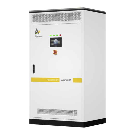
PRODUCT INTRODUCTION The system is equipped with local and remote monitoring and control functions. The system enables flexible scheduling of the power system through communication between the BMS, the H30 outdoor unit and the monitoring system. 2.3 Product Composition 2.3.1 Appearance For the appearance of the H30 energy storage system, please refer toFigure 2. - Page 23 PRODUCT INTRODUCTION Table 2-1 Product appearance of H30 View Description Front view 1. Indicators 2. HMI 3. Emergency stop button 4. Door locks 5. PCS equipment compartment air inlet 6. Decorative covers 7. Air conditioning inlet 8. Antennas Rear view 1.
-
Page 24: Description Of The Function Of The Indicator Light
PRODUCT INTRODUCTION 2.3.2 Description of the Function of the Indicator Light At the top of the outdoor cabinet HMI, there are four indicators showing the main operation status of the system: POWER, RUN, ON-GRID, and FAULT. Table 2-2 Description of LED indicators Status Color Description... -
Page 25: Outdoor Cabinet Size Parameters
PRODUCT INTRODUCTION 2.3.3 Outdoor Cabinet Size Parameters Figure 2-5 Outdoor unit dimensions 2.3.4 Interior Design of Outdoor Cabinets The system is an all-in-one design, combining the DC/AC module, DC/DC module, ATS module and energy storage battery system into one system, with the ATS module being an external wall-mounted solution (described in the installation section). - Page 26 PRODUCT INTRODUCTION Table 2-4 System configuration description View Description Front view 1. LED lighting 2. Air conditioning operating panel 3. High pressure box 4. DC/AC modules 5. PCS output switch 6. EMS 7. Terminal blocks and open sections 8. Batteries 9.
-
Page 27: Overview Of System Operating Switches
PRODUCT INTRODUCTION 2.3.5 Overview of System Operating Switches The H30 outdoor system contains the relevant operating switches, the high voltage box plastic case switch, the DC/DC module manual switch and the PCS output switch, the operating position of each switch in the system is shown in Figure 2-6, the function of each switch in the system is described in Table 2-5. -
Page 28: Cable Entrance Design
PRODUCT INTRODUCTION 2.3.6 Cable Entrance Design For easy cable connection on site, all cables between the devices inside the outdoor unit have been connected prior to delivery. The cables connecting the outdoor unit to the external equipment can enter the interior through the bottom cable entry or the side cable entry of the outdoor unit. -
Page 29: Product Components Introduction
PRODUCT COMPONENTS INTRODUCTION 3. Product Components Introduction 3.1 M38210-S Quick-Insert Back-Plug Battery Figure 3-1 Battery Diagram Table 3-1 Appearance Description Description battery Negative terminal BLMU Battery Positive terminal Boxes Fans Fixed lugs Handle... - Page 30 PRODUCT COMPONENTS INTRODUCTION Table 3-2 Technical Specifications Technical Description Notes Specifications Model M38210-S Cell formation method 12S2P Rated voltage 38.4V Voltage range 36~43.2V Maximum Rated capacity 210Ah charge/discharge current 0.5C Rated energy 8.1kWh Operating power <2W consumption Standby power Battery sleep <100mW consumption mode...
-
Page 31: M7790-S Quick-Insert Back-Plug Battery
PRODUCT COMPONENTS INTRODUCTION 3.2 M7790-S Quick-Insert Back-Plug Battery Figure 3-2 Battery Diagram Table 3-3 Appearance Description Description Battery Negative terminal BLMU Battery Positive terminal Boxes Fans Fixed lugs Handle... - Page 32 PRODUCT COMPONENTS INTRODUCTION Table 3-4 Technical Specifications Technical Description Notes Specifications Model M7790-S Cell formation 24S1P method Rated voltage 76.8V Voltage range 72 to 84.48V Max. charge/discharge Rated capacity 90Ah current: 1C Rated energy 6.9kWh Operating power <2W consumption Standby power <100mW Battery sleep mode consumption...
-
Page 33: High Voltage Box
PRODUCT COMPONENTS INTRODUCTION 3.3 High Voltage Box Figure 3-3 Diagram of the high voltage box Table 3-5 Appearance Description Description BLMU to BMU communication port Negative input (CAN) Positive input Dipswitch Mounting points × 4 SCADA screen power supply port AC powered Positive output DC powered... - Page 34 PRODUCT COMPONENTS INTRODUCTION Table 3-6 Technical Specifications Description Technical Specifications Model HV900105 Operating voltage range 200 ~ 900V Module connection M38210-S & M7790-S in series Rated current 105A Weight 20kg Power consumption <10W Color RAL7035...
-
Page 35: Ems4.0 Modules And Interface Definitions
PRODUCT COMPONENTS INTRODUCTION 3.4 EMS4.0 Modules and Interface Definitions Figure 3-4 Schematic diagram of the EMS4.0 module... - Page 36 PRODUCT COMPONENTS INTRODUCTION Table 3-7 Interface Definitions Interface Interface Definition Notes Name Telemeter (external normally Emergency stop signal closed) Telemetry (external normally Distribution main switch closed) (break - normally break feedback open close - normally closed) Telemetry (external normally Fire system failure closed) Fire alarms Telemetry (external normally...
- Page 37 PRODUCT COMPONENTS INTRODUCTION DI15~16 Undefined Wet node (active input) Remote control (normally open contact) Distribution main switch As the coil is connected, an breakers on/off signal with a closing time > 200 MS is required to achieve the breaking action Oiler start/stop Normally open nodes BMS fault signal feedback...
- Page 38 PRODUCT COMPONENTS INTRODUCTION RS485-3 Oilers Connected to COM1 of RS485-4 HMI/SCADA_FS SCADA_FS RS485-5 Electricity meters RS485-6 Charging piles RS485-7 Air conditioning Table 3-8 Technical Parameters Description Technical Specifications Dimensions (L × W × H) 490.6 × 323 × 161 mm Communication RS-485 ×...
-
Page 39: Pws2-30P-Cn Inverter
PRODUCT COMPONENTS INTRODUCTION 3.5 PWS2-30P-CN Inverter 30kW High Power Density Bi-directional Power Conversion System DC-Coupled Solution Figure 3-5 Dimensions of PWS2-30P-EX modular machine model (unit: mm) Figure 3-6 Appearance of front side of PWS2-30P-EX / PWS2-29P-EX... -
Page 40: Pds1-45K/Pds1-60K Dc/Dc Converter
PRODUCT COMPONENTS INTRODUCTION Name Description To connect positive power cables with Positive DC port the battery cabinet To connect negative power cables with Negative DC port the battery cabinet DC bus positive MC4 terminal*2 DC bus negative MC4 terminal*2 Signal interface area External communication interface AC terminal AC wiring... - Page 41 PRODUCT COMPONENTS INTRODUCTION Figure 3-8 PDS1-45K/PDS1-60K module external dimension diagram (unit: mm) Name Description Ground terminal Grounding protection wire fixed point To indicate the working status and ID Indicator light of the module To turn on/off the photovoltaic input. (To avoid power device life attenuation because of the impact current, do not PV input switch turn on the switch when the...
- Page 42 PRODUCT COMPONENTS INTRODUCTION Signal interface External communication interface Reserve signal interface Not supported at present Extraction and install module, not for Handle load-bearing Vent Fan cover and air duct vents 2 4 6 8 10 12 14 16 1 3 5 7 9 11 13 15 Figure 3-9 Communication panel and display panel Table 3-2 Technical parameters table Pin Definition...
- Page 43 PRODUCT COMPONENTS INTRODUCTION 7/8: R_485_2(Reserve) 7/8: 120 ohms matching resistor access signal for 485_2(Reserve); Short the Pin7 and Pin8 to 9/10: R_CAN(Reserve) enable it. 11/13: GND 9/10: 120 ohms matching resistor access signal 12/14: Dry in for CAN(Reserve); Short the Pin9 and Pin10 to enable it.
-
Page 44: Ats Pwd-100M
PRODUCT COMPONENTS INTRODUCTION 3.7 ATS PWD-100M Figure 3-10 PWD-100M-O Intelligent Switching Box External Dimensions Figure 3-11 PWD-100M-O front panel... - Page 45 PRODUCT COMPONENTS INTRODUCTION Name Description Pneumatic Prevents expansion when the internal temperature of pressure the module is high reducing valve Grid side inlet baffle (remove this baffle during Grid terminal installation) Load side Load side inlet baffle (remove this baffle during terminals installation) PCS side...
-
Page 46: Installation
INSTALLATION 4. Installation 4.1 Product Installation Before unpacking, please check the packaging for obvious signs of damage. If there are signs of damage, do not unpack, check the system model and contact your dealer as soon as possible. After unpacking, please check that each product is in good condition and contact your dealer as soon as possible if there is any obvious damage to the exterior. - Page 47 INSTALLATION Communication cable 390mm Batteries - Batteries M38210-S Battery (Optional) 33500600 (BT-BT) Quantity: 1 Inter-battery 40100088 communication Quantity: 4 lines Battery fixing screw Communication 4 X M6*14 cable 385mm Batteries - Batteries System Accessories 33201648 33201647 Fan power supply Quantity: 1 Quantity: 1 36000086 harness, quantity: 1...
- Page 48 INSTALLATION pre-installed in 2100mm (to be pre- the system) installed in the system) 33500627 (BT - 40100134 40200021 Quantity 1 Quantity: 2 Quantity: 2 41500004 BT-HV Screws GB/T9074.13 Nut GB/T 6177.1-2000 Quantity: 20 (communication) Stainless steel M8*25 Stainless steel body Tie 4*200mm nylon.
-
Page 49: H30 Outdoor Unit Installation
INSTALLATION 4.1.2 H30 Outdoor Unit Installation 4.1.2.1 Transport Conditions The various devices in the H30 outdoor unit, except for the battery section, are factory- installed and fixed to the inside of the outdoor unit. The following conditions need to be met to transport a mobile H30 outdoor unit: The doors of each cabinet of the H30 outdoor unit are locked tightly. - Page 50 INSTALLATION • The H30 outdoor unit should be transported, moved and set down slowly and steadily. Transportation is recommended. • Only place the H30 outdoor unit in a smooth place. The area should be free of any obstacles or bulges. 4.1.2.3 Pre-Transport Preparation for Forklifts The outer wooden box needs to be removed before transporting the H30 outdoor...
- Page 51 INSTALLATION The wiring holes are located on the bottom of the H30 outdoor unit and the cable is threaded into the cable slot through the wiring holes in the base. When the H30 outdoor unit needs to be fixed to the channel steel, Φ14 holes should be punched in the channel steel and screws should be used to fix the H30 outdoor unit to the channel steel, Please refer to Figure 4-3.
- Page 52 INSTALLATION Figure 4-5 Assembly diagram of the decorative cover Table 4-2 List of parts for the assembly of the decorative cover Description Front cover plate Back cover plate M4*8 stainless steel screws Table 4-3 Installation steps for decorative covers Step Description Remove the front cover plate, the rear cover plate and the M4*8 stainless Step 1...
-
Page 53: Wall Mounting Of Ats Equipment
INSTALLATION 4.1.3 Wall Mounting of ATS Equipment ATS wall mounting on the right side of the outdoor unit Figure 4-6 Illustration of ATS wall-mounted equipment installation Table 4-4 List of parts for ATS wall mounting Description ATS wall mounting plate (accessory in ATS box) ATS wall mounting plate mounting screws ATS equipment body Table 4-5 ATS wall mounting procedure... -
Page 54: Electrical Safety Class Installation
INSTALLATION 4.2 Electrical Safety Class Installation 4.2.1 Grounding Requirements 1. When the product is installed, the protective earth wire must be installed first. When dismantling, the protective earth wire must be removed last. 2. The system should be permanently earthed. Before operating the system, the electrical connections to the system should be checked to ensure that the system is reliably earthed. -
Page 55: Back-Plug System Power Cable Connection
INSTALLATION Figure 4-7 Diagram of the external earthing of the H30 outdoor system After the system is externally earthed, when opening the cabinet door to install the system the power cable connection for the back plug system must be connected first, it is strictly forbidden to connect the power cable after installing the battery pack. - Page 56 INSTALLATION Table 4-6 Battery to high-voltage box power line battery end access points Positive Negative Number Battery Battery Wiring Diagram Access Access Batteries Point Point BT1 B+ BT12 B- BT1 B+ BT11 B- BT7 B+ BT10 B-AA...
- Page 57 INSTALLATION BT1 B+ BT8 B- BT1 B+ BT8 B- BT1 B+ BT7 B-...
- Page 58 INSTALLATION BT1 B+ BT6 B- BT1 B+ BT5 B-...
- Page 59 INSTALLATION Figure 4-8 Diagram of wire harness and copper connection Table 4-7 Configuration of wire harness and copper connections Description Power cables (copper nose) Copper busbar M8 flange nut Triple combination screw M8...
-
Page 60: Battery Installation
INSTALLATION 4.2.4 Battery Installation Figure 4-8 Battery pack unpacking diagram Figure 4-10 Schematic diagram of the wire harness cover... - Page 61 INSTALLATION Table 4-8 Battery pack unpacking and installation procedure Step Description Step 1 Unpack all batteries and not lose the internal parts Step 2 Check the battery type on the battery label. Remove the harness cover mounting screw (M4*8 Phillips triple Step 3 combination screw) B with a Phillips screwdriver, then remove the harness cover A.
- Page 62 INSTALLATION Table 4-10 Battery assembly location diagram for various configurations Number of Batteries Batteries’ Installation Positions and Sequence Configured...
- Page 63 INSTALLATION...
- Page 64 INSTALLATION...
- Page 65 INSTALLATION...
-
Page 66: Meter
INSTALLATION Figure 4-11 Battery grounding diagram Before wiring, secure the battery to the battery holder with the three combination screws. The earth resistance should be less than 4ῼ. 4.2.5 Meter 4.2.5.1 Meter Installation Wiring Meter connection in different modes Grid Meter PV Meter Mode √... - Page 67 INSTALLATION Acrel ADL3000 Wiring Diagram For H30 installation, please wire as shown in the diagram (three phase four wire). Pay attention to the positive direction of the transformer and the position of the two lines of the transformer into the meter (e.g. Ia* to S1, Ia to S2). Wiring location description of Acrel three phase meter (with CT) Grid CT PV CT...
- Page 68 INSTALLATION Internet Internet cable_3(GreenWhite)----- cable_3(GreenWhite)-- 5A (EMS) RS485_A 5A(EMS) 5A(EMS) Internet cable_6(Green)-- Internet cable_6(Green)-- 5B (EMS) RS485_B 5B(EMS) 5B(EMS) Chint Meter Wiring Schematic Diagram For H30 installation, please wire as shown in the diagram (three phase four wire). Pay attention to the direction of the transformer and the position of the two wires of the transformer into the meter (e.g.
- Page 69 INSTALLATION Wiring of communication connected Meter (Chint) and EMS Grid Meter PV Meter Signal 24(Meter) - 5A(EMS) 24(Meter) - 5A(EMS) 5A (EMS) RS485_A 25(Meter) - 5B(EMS) 25(Meter) - 5B(EMS) 5B (EMS) RS485_B 4.2.5.2 Diagram of the Positive Direction of the Meter Wiring The positive direction corresponding to the positive value of the energy storage meter data is defaulted as shown above, with the H30 installed with a grid shut-off meter and a PV grid-connected meter.
- Page 70 INSTALLATION 4.2.5.3 Division of Communication Addresses for Meter Devices Lower limit of Upper limit Type of equipment of equipment electricity Description communicatio communicati meter n address on address communication address of the Grid gateway grid_gw_meter metered device is meter set from the lower address limit Energy storage...
- Page 71 INSTALLATION H30 has grid gate meters and PV grid-connected meters, please set the address as shown above; the device communication address is set from the low address; for example: 101 for grid gate meters and 121 for PV grid-connected meters. 4.2.5.4 Example of Setting the Communication Address of the Astronergy Meter DTSU666 4.2.5.5 Example of Setting the Communication Address of the Ankerys meter...
- Page 72 INSTALLATION Table 7 Description of the setup menu First-level Menu Second-level Menu Symbols Meaning Symbols Meaning Scope Corresponde ADDR nce address 1-247 setting 19200, 9600, Baud rate Baud 4800, 2400, selection 1200 Commu Calibration nication Parity None, Even options settings 645 high 6- digit table 000000-999999...
-
Page 73: Antenna Installation
INSTALLATION 4.2.6 Antenna Installation Figure 4-12 Diagram of antenna installation Table 4-11 List of antenna installation parts Description Antenna installation screws (reserved for the case) Antenna Antenna installation sheet metal... -
Page 74: Modular Phone Card Installation
INSTALLATION 4.2.7 4G Modular Phone Card Installation Figure 4-13 SIM card installation diagram Table 4-12 SIM card installation parts list Description 4G module body Thimble opening SIM card slot SIM card slot For SIM card installation, you need to press the thimble opening to pop out the card slot, then place the phone card into the slot and push the slot into the slot opening to complete the phone card installation. -
Page 75: Open The Cabinet Door
INSTALLATION • Apply the necessary earthing. • Insulate and cover the adjacent energized parts of the operating election, insulated fabric made of insulting material is used. 4.3.2 Open the Cabinet Door Open the door before the cable is connected Figure 4-14 Schematic diagram of the door opening procedure Table 4-13 Illustrative table of door opening steps Step Description... - Page 76 INSTALLATION The part numbers for the inter-battery communication cable and termination resistor are indicated in the illustration under the M7790-S part number. If the configuration is M38210-SC battery, please refer to the part list for the corresponding inter-cell communication cable and termination resistor. Table 4-14 Diagram showing the sequence of communication cable connections and the location of the termination resistors Diagram showing the sequence of communication...
- Page 77 INSTALLATION...
- Page 78 INSTALLATION...
- Page 79 INSTALLATION...
- Page 80 INSTALLATION...
- Page 81 INSTALLATION...
- Page 82 INSTALLATION...
- Page 83 INSTALLATION 1. Please use the termination resistor from the system accessory parts list and plug it into the last battery CAN port of each battery cluster, refer to Table 4-3 & Figure 4-3. 2. Connect the (CAN port) above the high voltage box to the high voltage box (LMU port) using the communication cable from the system accessories parts list, refer to Figure 4-3.
- Page 84 INSTALLATION 4.3.3.2 Communication Connection between ATS and PCS Figure 4-15 Communication connection between the ATS and a single PCS The communication between the ATS and the PCS uses CAN, and the communication cable of CAN uses super category 6 network cable, and the interface at both ends is RJ45 network port.
-
Page 85: Fan Power Supply Harness Connection
INSTALLATION 4.3.3.3 RRCR Connection Figure 4-15 Communication connection between EMS and RRCR The EMS is adapted to the German external device RRCR, which performs the action of adjusting the maximum feeder power with an external normally open signal, where DI11 is connected to RRCR_K1, DI12 to RRCR_K2, DI13 to RRCR_K3 and DI14 to RRCR_K4. -
Page 86: Pv Side Connection
INSTALLATION Figure 4-16 Fan power supply harness 4.3.5 PV Side Connection 1. Measure the PV voltage with a multimeter to ensure that the PV voltage is within the PV input voltage range of the DCDC module, which is 200-830V. . 2. - Page 87 INSTALLATION Table 4-15 Description of PV cables Rated Power Recommended Size for Copper-core DC Cables 45 kW 10 mm² For PV connections, please refer toFigure 4- and 错误!未找到引用源。 Figure 4-17 PV side wiring...
-
Page 88: Ac Side Connection
INSTALLATION Figure 4-18 PV inlet and routing path 1. Connect the positive PV harness of the PV string through the PV+ inlet hole and connected to the positive terminal of the DCDC module Refer to Figure 4-24. 2. Connect the negative PV harness of the PV string to the negative terminal of the DCDC module by passing it through the PV-inlet hole.Refer to Figure 4-24. - Page 89 INSTALLATION 3. Use a multimeter to measure and ensure that there is no voltage on the cable connected to the copper strip. 4. Phases L1 / L2 / L3 and N of the AC circuit breaker on the PCS side of the H30 outdoor unit, is connected to the PCS side of the ATS, phases L1 / L2 / L3 and N respectively 5.
-
Page 90: Sealed Inlet And Outlet Holes
INSTALLATION 4.3.7 Sealed Inlet and Outlet Holes Once the wiring is complete, the inlet and outlet holes of the equipment are sealed with fireproof mortar. 4.3.8 ATS External Wiring Instructions Figure 4-20 Illustration of ATS and GRID wiring... - Page 91 INSTALLATION Figure 4-21 Illustration of ATS and LOAD wiring 1. Measuring the GRID and LOAD wiring positions of the ATS with a multimeter; 2. Ensure that there is no voltage at the GRID and LOAD wiring positions of the ATS; 3.
-
Page 92: Checks Before System Start-Up
CHECKS BEFORE SYSTEM START-UP 5. Checks before System Start-up The following steps are required after the system has been wired and before it can be started up for operation: 1. Measure the input voltage of the high voltage box with a multimeter. The normal voltage range should be 700~830V;... -
Page 93: Technical Service Contact
TECHNICAL SERVICE CONTACT 6. Technical Service Contact If you have technical questions about our products, please contact our service hotline. The contact information is provided at the end of this manual. Please provide the following information for our technical service team to help you with the necessary assistance: System configuration Product serial number (SN) -
Page 94: System Installation Torque Force Table
External earth M10*35 Carbon steel, grade 1pcs 15±10% fixing 4.8 bolts, white zinc plated Please follow the recommended torque values in the table and provide feedback to the AlphaESS engineers if there are any special or unusual circumstances. - Page 95 SYSTEM INSTALLATION TORQUE FORCE TABLE...
Need help?
Do you have a question about the STORION-H30-O and is the answer not in the manual?
Questions and answers