Table of Contents
Advertisement
Quick Links
Advertisement
Table of Contents

Related Manuals for AlphaESS STORION-H30


Summary of Contents for AlphaESS STORION-H30
- Page 1 INSTALLATION MANUAL OF ENERGY STORAGE SYSTEM STORION-H30...
-
Page 2: Copyright Statement
COPYRIGHT STATEMENT Copyright Statement The copyright of this manual is owned by Alpha ESS Co., Ltd. and all rights re- served. Without written permission of the Company, no unit or individual is al- lowed to extract or copy any part or the entirety of the content within this docu- ment. -
Page 3: Note
NOTE Note The products, services or features, etc. should be subject to AlphaESS commercial contracts and terms. Please note that some of the products, services or features described in this document may not be included in your purchase or use. Al-... -
Page 4: Preface
PREFACE Preface After years of dedicated research and development by AlphaESS, the STORION- H30 lithium-ion battery indoor energy storage system has been successfully applied to many sites. This high-tech product with excellent quality and stable performance, is widely used in electric power supply industry today. -
Page 5: Terminology
TERMINOLOGY Terminology 1. Battery Management Systems (BMS) It is used to monitor the operating information (such as voltage, current, temper- ature, battery protection parameters, etc.) of battery cells, battery packs, and sys- tem units, and intelligently evaluate the state of charge (SOC) and health status (SOH) and accumulated energy to protect the safety of battery 2. - Page 6 TERMINOLOGY 7. Grid-connected Systems Grid-connected systems usually consist of photovoltaic arrays, H30 indoor units, battery system, and the grid. When the electric energy generated by the PV string is sufficient, the surplus elec- tric energy can be fed into the grid. Conversely, when the electric energy gener- ated by the PV string and battery system is insufficient, the grid can supply power to the load.
-
Page 7: Table Of Contents
TABLE OF CONTENTS Table of Contents Copyright Statement .................... 1 Note ........................2 Preface ........................3 Terminology ......................4 Table of Contents ....................6 1. Safety Instructions ................... 9 1.1 Operators’ Qualifications ................. 9 1.2 Personal Safety ..................10 1.3 Product Safety ..................11 1.4 Electrical Safety .................. - Page 8 SAFETY INSTRUCTIONS 2.3.3 Indoor Cabinet Size Parameters ..................24 2.3.4 Interior Design of Indoor Cabinets ................... 24 2.3.5 Overview of Equipment Operating Switch Positions ..........26 2.3.6 Cable Entrance Design ......................27 3. Product Components Introduction .............. 29 3.1 M38210-S Quick-Insert Back-Plug Battery ........... 29 3.2 M7790-S Quick-Insert Back-Plug Battery ..........
- Page 9 TABLE OF CONTENTS 4.3.7 Sealed Inlet and Outlet Holes ..................... 87 4.3.8 Description of the External Wiring of the ATS .............. 87 5. Checks before System Start-up ..............89 6. Technical Service Contact ................90 7. System Installation Torque Force Table............. 91...
-
Page 10: Safety Instructions
In the event of a fault occurring during normal system operation, please begin by trou- bleshooting using the provided fault checklist. If the problem remains unresolved, please contact an AlphaESS engineer promptly and make sure to turn the system (bat- teries, H30 indoor unit etc.) off before the AlphaESS engineer replies. -
Page 11: Personal Safety
SAFETY INSTRUCTIONS 1.2 Personal Safety • Place clear signs next to the circuit breakers of PV, battery, H30 indoor unit and the distribution box to prevent accidents caused by accidental switching. • Place warning signs or set up safety warning strips around the operating area. •... -
Page 12: Product Safety
SAFETY INSTRUCTIONS Table 1-1 Protective Equipment Name Name Safety shoes Protective goggles Safety helmet Dust masks Safety gloves 1.3 Product Safety • Warning signs contain important information for the safe operation of the product; it is important to make sure they are clear and visible. Any damage should be avoided, and if any occurs, the signs should be replaced immediately. -
Page 13: Wiring Requirements
SAFETY INSTRUCTIONS 1.4.2 Wiring Requirements 1. For safety, connect the power cable from the battery to the high-voltage box before assembling the system battery following the earth wire connection. 2. Cables used in high-temperature environments may cause insulation deterioration and breakage. The distance between the cable and heat-generating device or heat source area should be at least 30mm. - Page 14 SAFETY INSTRUCTIONS No condensation inside the Condensatio Yes/ product within a None None relative humidity range of 0 to 90%. When the Low altitude altitude exceeds 3000m above sea level, the maximum limit Elevati should be reduced High altitude 3000 3000 3000 according to...
-
Page 15: Transportation Requirements
SAFETY INSTRUCTIONS 1.6 Transportation Requirements When moving large products that are still in transport boxes or pallets, use a forklift to lift the cabinet from the bottom and move it. Please refer toFigure 1. When transporting batteries, to avoid dropping the product due to excessive weight, it is recommended to have 2 people carry it. - Page 16 SAFETY INSTRUCTIONS Figure 1-2 Large product handling Figure 1-3 Small product handling Figure1-4 Schematic diagram of the location of the no handling points A and B Do not grab the components in the red circle while transporting the battery. When handling the battery, do not grab it by the connectors marked as A and B. Instead, apply force to the front handle and the box when handling it.
-
Page 17: Mounting Position
SAFETY INSTRUCTIONS 1.7 Mounting Position 1.7.1 H30 Indoor Unit When installing the H30 indoor unit, ensure that there is sufficient space for ventilation and heat dissipation as well as installation and maintenance. For detailed installation requirements, please refer toFigure 1. Figure 1-5 H30 indoor unit installation location A ≥... -
Page 18: External Ats Installation
SAFETY INSTRUCTIONS 1.7.2 External ATS Installation Figure 1-6 ATS wall-mounted solution installation position A ≥ 600mm, ATS has sufficient space for operation and maintenance. -
Page 19: Product Introduction
PRODUCT INTRODUCTION 2. Product introduction 2.1 Product Description 2.1.1 Schematic Diagram of the Grid-Connected System The H30 energy storage system supports grid-connected application modes. A diagram of the grid-connected system is shown below: Figure 2-1 Schematic diagram of the DC grid-connected system Figure 2-2 Schematic diagram of the AC grid-connected system... -
Page 20: Product Features
The dotted lines indicate the communication lines, the solid lines indi- cate the power lines. 2.2 Product Features Lithium iron phosphate batteries produced by AlphaESS are characterised by their long life and high reliability and are capable of meeting the requirements of a wide range of energy storage systems. -
Page 21: Products Composition
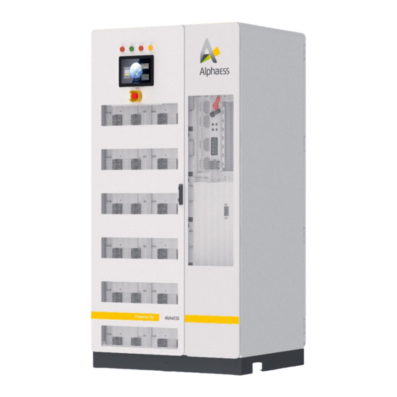
PRODUCT INTRODUCTION The system enables flexible scheduling of the power system through communication between the BMS, the H30 indoor unit and the monitoring system. 2.3 Products Composition 2.3.1 Appearance Introduction For the appearance of the H30 energy storage system, please refer toFigure 2. Figure 2-4 H30 system *The above pictures are for reference only, please refer to the actual product received! - Page 22 PRODUCT INTRODUCTION Table 2-1 Product appearance of H30 View Description Front view 1. Indicators 2. HMI 3. Emergency stop button 4. Battery compartment air outlet 5. Equipment compartment air outlet 6. Door locks 7. Battery compartment front door 8. Front door of the equipment compartment 9.
-
Page 23: Description Of The Function Of The Indicator Light
PRODUCT INTRODUCTION Right view 1. Inlet and outlet holes Rear view 1. Rear door of the equipment compartment 2. Battery compartment rear door 3. Battery compartment air inlet 4. Equipment compartment air inlet 5. door locks 6. Grounding position *The above pictures are for reference only, please refer to the physical received! 2.3.2 Description of the Function of the Indicator Light At the top of the indoor HMI there are four indicators showing the main operating... - Page 24 PRODUCT INTRODUCTION Table 2-2 Description of LED indicators Name Colour Description Always on when the system is powered, always off when the POWER system is not powered Always on when the system operates normally with power output, Green always off when the system is in standby or switched off Always on when the system is connected to the grid, always off ON-GRID Yellow...
-
Page 25: Indoor Cabinet Size Parameters
PRODUCT INTRODUCTION 2.3.3 Indoor Cabinet Size Parameters Figure 2-5 Indoor unit dimensions 2.3.4 Interior Design of Indoor Cabinets The system is an all-in-one design, combining the DC/AC module, DCDC module, ATS module and energy storage battery system into one system, with the ATS module be- ing an external wall-mounted solution (described in the installation section). - Page 26 PRODUCT INTRODUCTION Table 2-4 System configuration description View Description Front view 1. Terminal blocks and distribution boxes 2. High voltage box 3. DC/DC modules 4. DC/AC modules 5. PCS output switch 6. EMS 7. Batteries 8. Earthing row Front view 1.
-
Page 27: Overview Of Equipment Operating Switch Positions
PRODUCT INTRODUCTION 2.3.5 Overview of Equipment Operating Switch Positions The H30 indoor system contains the relevant operating switches, the high voltage box plastic case switch, the DC/DC module manual switch, the PCS output switch, the op- erating position of each switch in the system is shown in Figure 2-6, the function of each switch in the system is described in Table 2-5. -
Page 28: Cable Entrance Design
PRODUCT INTRODUCTION Table 2-5 Description of equipment switches Equipment switches Description High voltage box plastic Control battery DC system power-up case switch Manual switching of DC/DC Control the input to the PV modules PCS output switch Control PCS AC output 2.3.6 Cable Entrance Design For easy cable connection on site, all cables between the devices inside the indoor unit have been connected prior to delivery. - Page 29 PRODUCT INTRODUCTION Table 2-6 Description of inlet and outlet ports Description Size Inlet and outlet holes on the 57*128mm left side of the system Inlet and outlet holes on the 57*128mm right side of the system...
-
Page 30: Product Components Introduction
PRODUCT COMPONENTS INTRODUCTION 3. Product Components Introduction 3.1 M38210-S Quick-Insert Back-Plug Battery Figure 3-1 Battery diagram Table 3-1 Appearance Description Description Battery Negative terminal BLMU Battery Positive terminal Boxes Fans Fixed lugs Handles... - Page 31 PRODUCT COMPONENTS INTRODUCTION Table 3-2 Technical specifications Technical Description Notes Specifications Model M38210-S Cell formation method 12S2P Rated voltage 38.4V Voltage range 36~43.2V Maximum Rated capacity 210Ah charge/discharge current: 0.5C Rated energy 8.1kWh Operating power <2W consumption Sleep mode power Battery sleeping <100mW consumption...
-
Page 32: M7790-S Quick-Insert Back-Plug Battery
PRODUCT COMPONENTS INTRODUCTION 3.2 M7790-S Quick-Insert Back-Plug Battery Figure 3-2 Battery diagram Table 3-3 Appearance Description Description Battery Negative terminal BLMU Battery Positive terminal Boxes Fans Fixed lugs Handle... - Page 33 PRODUCT COMPONENTS INTRODUCTION Table 3-4 Technical specifications Technical Description Notes Specifications Model M7790-S Cell formation 24S1P method Rated voltage 76.8V Voltage range 72 to 84.48V Max. charge/discharge Rated capacity 90Ah current 1C Rated energy 6.9kWh Operating power <2W consumption Sleep mode power <100mW Battery sleep mode consumption...
-
Page 34: High Voltage Box
PRODUCT COMPONENTS INTRODUCTION 3.3 High Voltage Box Figure 3-3 Diagram of the high voltage box Table 3-5 Appearance Description Description BLMU to BMU communication Negative input port (CAN) Positive input Dipswitch SCADA screen power supply Mounting points × 4 port AC power Positive output DC power... - Page 35 PRODUCT COMPONENTS INTRODUCTION Table 3-6 Technical specifications Description Technical Specifications Model HV900105 Operation voltage range 200 ~ 900V Module connection M38210-S & M7790-S in series Rated current 105A Weight 20kg Power consumption <10W Colour RAL7035...
-
Page 36: Ems4.0 Modules And Interface Definitions
PRODUCT COMPONENTS INTRODUCTION 3.4 EMS4.0 Modules and Interface Definitions Figure 3-4 Schematic diagram of the EMS4.0 module... - Page 37 PRODUCT COMPONENTS INTRODUCTION Table 3-7 Interface definitions Interface Interface Definition Notes Name Remote signal (external normally Emergency stop signal closed) Remote signal (external normally Distribution main switch break closed) (break - normally open feedback close - normally closed) Remote signal (external normally Fire system failure closed) Fire alarms...
- Page 38 PRODUCT COMPONENTS INTRODUCTION DI15~16 Undefined Wet node (active input) Remote control (normally open contact) Distribution main switch As the coil is connected, an breakers on/off signal with a closing time > 200 MS is required to achieve the breaking action Oiler start/stop Normally open nodes BMS fault signal feedback...
-
Page 39: Pws2-30P-Cn Inverter
PRODUCT COMPONENTS INTRODUCTION Connected to COM1 of RS485-4 HMI/SCADA_FS SCADA_FS RS485-5 Electricity meters RS485-6 Charging piles RS485-7 Air conditioning 3.5 PWS2-30P-CN Inverter 30kW High Power Density Bi-directional Power Conversion System DC-Coupled Solu- tion Figure 3-5 Dimensions of PWS2-30P-EX modular machine model (unit: mm) - Page 40 PRODUCT COMPONENTS INTRODUCTION Figure 3-6 Appearance of front side of PWS2-30P-EX / PWS2-29P-EX Name Description To connect positive power cables to the Positive DC port battery cabinet To connect negative power cables to the Negative DC port battery cabinet DC bus positive MC4 terminal*2 DC bus negative MC4 terminal*2...
-
Page 41: Pds1-45K/Pds1-60K Dc/Dc Converter
PRODUCT COMPONENTS INTRODUCTION 3.6 PDS1-45K/PDS1-60K DC/DC Converter Figure 3-7 PDS1-45K/PDS1-60K module model panel appearance diagram Figure 3-8 PDS1-45K/PDS1-60K module external dimension diagram (unit: mm) Name Description Ground terminal Grounding protection wire fixed point To indicate the working status and ID of Indicator light the module... - Page 42 PRODUCT COMPONENTS INTRODUCTION To turn on/off the PV input. (To avoid power device life attenuation PV input switch because of the impact current, do not turn on the switch when the PV voltage is higher than 100V.) MC4 terminal*6 PV positive input port To connect positive power cables to the photovoltaic module MC4 terminal*6...
- Page 43 PRODUCT COMPONENTS INTRODUCTION 2 4 6 8 10 12 14 16 1 3 5 7 9 11 13 15 Figure 3-9 Communication panel and display panel Table 3-8 Technical parameter table Pin Definition Description Power: Module power indicator Run: Module run indicator Indicator light Fault: Module fault indicator ID0-ID5: Module six-digit ID code, used to...
-
Page 44: Ats Pwd-100M
PRODUCT COMPONENTS INTRODUCTION 15/16:DO OC output (Reserve). 17: Grounding screw holes of RS485 communication cable shielding layer. Reserve signal interface 1/2: CAN differential signal (Reserve, not 1: CAN_H(Reserve) supported at present). 2: CAN_L(Reserve) 3/4: RS485_2 differential signal (Reserve, not 3: 485A_2(Reserve) supported at present). - Page 45 PRODUCT COMPONENTS INTRODUCTION Figure 3-11 PWD-100M-O front panel Name Description Pneumatic Prevents expansion when the internal temperature of the pressure module is high reducing valve Grid side inlet baffle (remove this baffle during Grid terminal installation) Load side Load side inlet baffle (remove this baffle during terminals installation) PCS side...
-
Page 46: Installation
INSTALLATION 4. Installation 4.1 Product Installation Before unpacking, please check the package for obvious signs of dam- age. If there are signs of damage, do not unpack, check the system model and contact your dealer as soon as possible. After unpacking, please check that each product is in good condition and contact your dealer as soon as possible if there is any visible damage to the exterior. - Page 47 INSTALLATION Batteries - Batteries M38210-S Battery (Optional) 33500600(BT-BT) Quantity: 1 Inter-battery 40100088 communication Quantity: 4 lines Battery fixing screw Communication 4 X M6*14 cable (385mm) Batteries - Batteries System Accessories 33201648 33201647 Fan power supply harness Quantity: 1 Quantity: 1 36000086 Quantity: 1 Battery - High...
- Page 48 INSTALLATION pre-installed in 2100mm (to be pre- the system) installed in the system) 33500627 (BT - 40100134 40200021 Quantity: 1 Quantity: 2 Quantity: 2 41500004 BT-HV Screws GB/T9074.13 Nut GB/T 6177.1-2000 Quantity: 20 (communication) Stainless steel M8*25 Stainless steel body Tie 4*200mm nylon Phillips socket M8 Hexagonal flange...
-
Page 49: H30 Indoor Unit Installation
INSTALLATION 4.1.2 H30 Indoor Unit Installation 4.1.2.1 Transport Conditions The various devices in the H30 indoor unit, except for the battery section, are fixed in the indoor unit before delivery When transporting indoor units, take care of transport. The following conditions need to be met to transport a mobile H30 in- door unit: Each cabinet door of the H30 indoor unit is locked tightly. - Page 50 INSTALLATION • The H30 indoor unit should be transported, moved and set down slowly and steadily. Attempted transport is recommended. • Should only place the H30 indoor unit in a smooth place. The area should be free of any obstacles or bulges. 4.1.2.3 Pre-Transport Preparation for Forklift Trucks The first step before transporting the H30 indoor unit by forklift truck is to remove the outer wooden box and the second step is to remove the decorative cover.
- Page 51 INSTALLATION The decorative cover is reversed at the end of the indoor unit installation wiring operation. Figure 4-2 Schematic diagram of forklift transport in two directions 4.1.2.4 H30 Equipment Installation After moving the H30 indoor unit to the installation position with a forklift or other tool, secure its base with M12 screws, seeFigure 4-.
- Page 52 INSTALLATION When the H30 indoor unit needs to be fixed to the channel steel, Φ14 holes should be punched in the channel steel and screws should be used to fix the H30 indoor unit to the channel steel, please refer to Figure 4-3. When the H30 indoor unit needs to be fixed to the concrete floor, holes need to be drilled in the floor and screws need to be used to fix the H30 indoor unit to the concrete floor, please refer toFigure 4- Connect the grounding point on the lower rear door of...
-
Page 53: Wall-Mounting Of Ats Equipment
INSTALLATION Figure 4-6 diagram of the decorative cover assembly Table 4-4 List of parts for the decorative cover assembly Description Front cover plate Back cover plate M4*8 stainless steel screws Table 4-5 Installation steps for decorative covers Step Description Remove the front cover plate, the rear cover plate and the M4*8 stainless Step 1 steel screws from the cabinet Assemble the front and rear cover panels to the indoor cabinet in the... -
Page 54: Electrical Safety Installation
INSTALLATION Figure 4-2 Illustration of ATS wall-mounted equipment installation Table 4-6 List of parts for STS wall mounting Description ATS wall mounting plate (accessory in STS box) ATS wall mounting plate mounting screws ATS equipment body Table 4-7 ATS wall mounting procedure Step Description using four ATS wall mounting plate mounting screws to install ATS wall... -
Page 55: External Earthing Of The System
INSTALLATION 3 Damage to the earth conductor is prohibited. It is strictly forbidden to install the system before grounding, the first step is to ground the system externally, followed by the connection of the power cable of the back-plug system, after which the rest of the system is installed. 4.2.2 External Earthing of the System The H30 indoor system includes internal earthing and external earthing, and the earth- ing of the system's internal equipment is completed prior to delivery. -
Page 56: Back-Plug System Power Cable Connection
INSTALLATION Figure 4-9 Diagram of the external earthing of the H30 indoor system After the system is externally earthed, before opening the cabinet door to install the system, the power cable of the back plug system must be connected first, it is strictly forbidden to connect the power cable after installing the battery pack. - Page 57 INSTALLATION BT1 B+ BT12 B- BT1 B+ BT11 B- BT1 B+ BT10 B- BT1 B+ BT9 B-...
- Page 58 INSTALLATION BT1 B+ BT8 B- BT1 B+ BT7 B- BT1 B+ BT6 B-...
- Page 59 INSTALLATION BT1 B+ BT5 B- Figure 4-10 Diagram of wire harness and copper connection Table 4-9 Configuration of wire harness and copper connections Description Power cables (system comes pre-assembled) Copper bar (system to be pre-installed) M8 flange nut (in system accessories) Triple combination screw M8 (in system accessories)
-
Page 60: Battery Installation
INSTALLATION 4.2.4 Battery Installation Figure 4-10 Battery pack unpacking diagram Step Description Step 1 Unpack all batteries and do not lose the internal parts Step 2 Check the battery type on the battery label. Remove the harness cover mounting screws (M4*8 Phillips triple Step 3 combination screws) B with a Phillips screwdriver, then remove the harness cover A. - Page 61 INSTALLATION Figure 4-11 Schematic diagram of the wire harness cover Table 4-11 Wire Harness Cover Related Materials Table Description Wire harness cover Wire harness cover mounting screws (M4*8 Phillips triple combination screws)
- Page 62 INSTALLATION Table 4-12 Battery installation diagram Number of Batteries Batteries’ Installation Positions and Sequence Configured...
- Page 63 INSTALLATION...
- Page 64 INSTALLATION...
- Page 65 INSTALLATION...
-
Page 66: Meter
INSTALLATION Figure 4-13 Battery grounding diagram Before wiring, secure the battery to the battery holder with the 4 triple combi- nation screws. The earth resistance should be less than 4ῼ. 4.2.5 Meter 4.2.5.1 Meter Installation Wiring Meter connection in different modes Grid Meter PV Meter Mode... - Page 67 INSTALLATION PIC_7 (Acrel ADL3000) wiring diagram For H30 installation, please wire as shown in the diagram(three phase four wire). Pay attention to the positive direction of the transformer and the position of the two lines of the transformer into the meter (e.g. Ia* to S1, Ia to S2). Wiring location description of Acrel three phase meter (with CT) Grid CT PV CT...
- Page 68 INSTALLATION PIC_8 (Chint Meter) PIC_8 (Chint) wiring schematic diagram For H30 installation, please wire as shown in the diagram (three phase four wire). Pay attention to the direction of the transformer and the position of the two wires of the transformer into the meter (e.g.
- Page 69 INSTALLATION 4.2.5.2 Diagram of the Positive Direction of the Meter Wiring The positive direction corresponding to the positive value of the energy storage meter is defaulted as shown above. H30 is installed with a grid shut-off meter and a PV grid- connected meter;...
- Page 70 INSTALLATION Energy storage and grid- ess_gw_meter Ibid connected meter Photovoltaic grid- pv_gw_meter Ibid connected meter Charging station cp_gw_meter Ibid gateway meter Wind energy grid connection wn_gw_meter Ibid point gateway meter Load shut-off load_gw_meter Ibid meter Energy storage ess_in_gw_me- internal self- Ibid consumption meter...
- Page 71 INSTALLATION H30 has grid gate meters and PV grid-connected meters, please set the address as shown above; the device communication address is set from the low address; for example: 101 for grid gate meters and 121 for PV grid-connected meters. 4.2.5.4 Example of Setting the Communication Address of the Astronergy Meter DTSU666 4.2.5.5 Example of Setting the Communication Address of an Ankerys Meter...
- Page 72 INSTALLATION Table 7 Description of the setup menu First-level Menu Second-level Menu Symbols Meaning Symbols Meaning Scope Correspond- ADDR ence ad- 1-247 dress setting Baud rate 19200, 9600, 4800, Baud selection 2400, 1200 Commu- Validation Parity None, Even nication Selection settings 645 high 6- digit table...
-
Page 73: Electrical Connections
INSTALLATION Electrical Connections 4.3.1 Safety Precautions The following safety precautions should be observed throughout the electrical connec- tion process and all other operations on equipment such as energy storage systems. • Disconnect all external connections of the energy storage integrated system and the connection with the internal power supply of the device. -
Page 74: Communication Cable Connection
INSTALLATION 4.3.3 Communication Cable Connection 4.3.3.1 Battery Side Connection Depending on the configuration differences between items, configure the communi- cation wires among batteries (see Table 4-1 Parts List for specific part numbers) and the sequence of connection and the location of the termination resistors are shown in Table 4-14: Schematic diagram of connection sequence of communication cable and the location of the termination resistors. - Page 75 INSTALLATION Table 4-14 Schematic diagram of connection sequence of communication cable and the location of the termination resistors Diagram showing the sequence of communication Number of cable connections and the location of the termination batteries resistors...
- Page 76 INSTALLATION...
- Page 77 INSTALLATION...
- Page 78 INSTALLATION...
- Page 79 INSTALLATION...
- Page 80 INSTALLATION...
- Page 81 INSTALLATION...
- Page 82 INSTALLATION • Please use the terminal resistance from the System Accessories parts list and plug it into the CAN port of last battery of each battery cluster. • Connect the (CAN port) on top of the high voltage box with the (LMU port) high voltage box by using the communication cable from the system accessories parts list.
- Page 83 INSTALLATION 4.3.3.2 Communication Connection between ATS and PCS Figure 4-14 Communication connection between ATS and a single PCS The communication between the ATS and the PCS uses CAN, which uses super cate- gory 6 network cable, and the interface at both ends is RJ45 network port. When there is only one ATS and one PCS in the system for networking, the dip switches 1 and 2 of the ATS should be dialed down and 3 and 4 dialed up, while the dip switch 4 of the PCS should be dialed up and all other dip switches of the PCS should be dialed down.
-
Page 84: Fan Power Supply Harness Connection
INSTALLATION The EMS is adapted to the German external device RRCR, which performs the action of adjusting the maximum feed-in power with an external normally open signal, where DI11 is connected to RRCR_K1, DI12 to RRCR_K2, DI13 to RRCR_K3 and DI14 to RRCR_K4. -
Page 85: Pv Side Connection
INSTALLATION 4.3.5 PV Side Connection • Measure the PV voltage with a multimeter to ensure that the PV voltage is within the PV input voltage range of the DCDC module, which is 200-830V. • Disconnect the PV circuit breaker from the DCDC module and make sure that there is no voltage between the positive and negative PV inputs before wiring. - Page 86 INSTALLATION Figure 4-18 PV inlet and routing path • Connect the positive PV string harness through the bottom of the cabinet, through the wiring path shown in Figure 4-24, with the positive terminal of the DCDC mod- ule, see Figure 4-24 for wiring diagram. •...
-
Page 87: Ac Side Connection
INSTALLATION 4.3.6 AC Side Connection 4.3.6.1 AC Side with ATS Wiring • Ensure that the AC side is wired in the correct phase sequence. • Disconnect the AC circuit breaker in the H30 indoor unit. • Use a multimeter to measure and ensure that there is no voltage on the cable con- nected to the copper strip. -
Page 88: Sealed Inlet And Outlet Holes
INSTALLATION Table 4-16 AC Cable Description Rated Power Recommended Size of Copper-core Cable 30 kW ≥16 mm² Before wiring, use a multimeter to measure the AC voltage side and ensure that there is no voltage at the connection point! 4.3.7 Sealed Inlet and Outlet Holes Once the wiring is complete, the inlet and outlet holes of the system should be sealed with fireproof mortar. - Page 89 INSTALLATION Figure 4-27 Illustration of ATS and LOAD wiring 1. Measure the wiring positions of GRID and LOAD of ATS with a multimeter; 2. Ensure that there is no voltage at the GRID and LOAD wiring positions of the ATS; 3.
-
Page 90: Checks Before System Start-Up
CHECKS BEFORE SYSTEM START-UP 5. Checks before System Start-up The following steps are required after the system has been wired and before starting 1. Measure the input voltage of the high voltage box with a multimeter. The normal voltage range should be 700~830V; 2. -
Page 91: Technical Service Contact
TECHNICAL SERVICE CONTACT 6. Technical Service Contact If you have any technical questions about our products, please contact our service hot- line. The contact information is provided at the end of this manual. Please provide the following information to help you with the necessary assistance: A. -
Page 92: System Installation Torque Force Table
Nut, flange, M8. and negative External earth M10*35 Stainless steel screws 1pcs 15±10% fixed Please follow the recommended torque force value in the table and pro- vide feedback to the AlphaESS engineers if there are any special or unusual cir- cumstances. - Page 93 SYSTEM INSTALLATION TORQUE FORCE TABLE...
Need help?
Do you have a question about the STORION-H30 and is the answer not in the manual?
Questions and answers