
Related Manuals for Tektronix 1A5


Summary of Contents for Tektronix 1A5
- Page 1 INSTRUC TION M AN U AL TYPE DIFFERENTIAL AMPLIFIER PLUG-IN UNIT Tektronix, Inc. S.W. Millikan Way • P. O. Box 500 • Beaverton, Oregon 97005 • Phone 644-0161 • Cables: Tektronix 070-0638-00...
- Page 2 © 1967 by T ronix, Inc., on, Oregon. P nted in the United ates of America. All rights reserved. Contents of th s publication may not be reproduced in any form without permission of the c ight owne Type 1A5 man.
- Page 3 CONTENTS ecti on 1 Characte ion 2 Operating instructions ion 3 rcuit Des ption ion 4 Main enance ion 5 formance Check ion 6 librat Abbrevia ns and S rts Ordering Information ion 7 lectr ical P rts List Mechanical P rts L st Informat on 8...
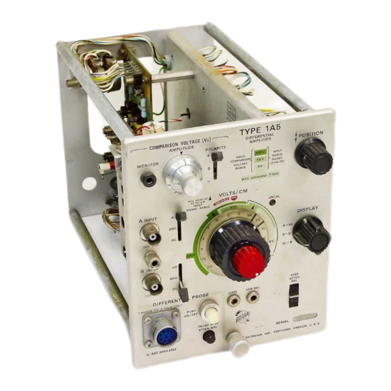
- Page 4 Fig. 1- 1. Type 1A5 D fferen ial Am ifier P In Unit. Type 1A5...
- Page 5 Differential Comparator Operation: Observation unit designed for use in Tektronix Type 544, 546, 547 and measurement of a signal by comparison against a cali 556 Oscilloscopes and their rackmount equivalents, it can brated internal DC source. be operated in all other 540 series and in all 530, 550 and 580 series oscilloscopes with some reduction in performance.
- Page 6 Characteristics — Type 1 A5 TABLE 1-1 (cont) Electrical Characteristics Supplemental Information Characteristic Performance Requirement Common-Mode Rejection Ratio See Fig. 1 -1 DC Coupled > 20,000:1, DC to 100 kHz, 0°C to 50°C 4- and — 5-V signal applied 1 mV / cm to 20 mV / cm ( ×1 ) >10,000:1, 100 kHz to 1 MHz, 0°C to 50°C;...
- Page 7 ACCESSORIES Standard accessories supplied with the Type 1A5 Dif The Type 1A5 Differential Amplifier is 14 ½ inches long, ferential Amplifier consist of two manuals. 4 ¼ inches wide and 6 ¼ inches high. It is designed to fit...
- Page 9 CMRR of 10 — .001 or 10,000:1. This section contains a description of differential ampli fiers in general, of the Type 1A5 Differential Amplifier con Amplitude and Common-Mode Rejection trols, connectors and indicators, and of the Type 1A5 Differ ...
- Page 10 Operating Instructions — Type 1A5 g. 2-1. Type 1A5 front panel.
- Page 11 DC reference. NOTE A INPUT BNC connector. A positive signal applied causes an upward deflection. fer to the front panel of a Type 1A5 Differen tial Amplifier to fol ow the color-related descrip B INPUT BNC connector. A pos...
- Page 12 Operating Instructions — Type 1A5 Source Impedance 10 kΩ 10.00 V Generators 5 kΩ Source Impedance 0.05 V Apparent DC CMRR 200:1 (See graph for effect on AC CMRR) FREQUENCY Fig. 2-2. The effect of difference in source impedance upon apparent CMRR.
- Page 13 Operating Instructions — Type 1A5 Source Impedance 100 Ω 9.9990 V 1 MΩ stray and lead 10.0000 V capacitance Generators MΩ 9.9995 50 Ω Source Impedance B - A = .0005 V Apparent DC CMRR 20,000:1 (See graph for effect on AC CMRR) FREQUENCY Fig.
- Page 14 Operating Instructions — Type 1A5 Fig. 2-4. Capacitive and inductive reactance versus frequency.
- Page 15 Fig. 2-6. Connecting a differential amplifier across a circuit. Type 1A5. A white dot on this knob indicates the deflec ground shown in (C) is not essential to the measurement.
- Page 16 Voltage Range translations printed on the green arcs and on the separate color cod ing explanation near the top right of the Type 1A5 front panel. CAUTION The difference between the voltages into the A and В INPUT connectors must never exceed the Fig.
- Page 17 Operating Instructions — Type 1A5 medium green dark green light green Sensitivity Indicator Gain Switching Knob- Range Indicators “ Retained" Switching- Position Indicators Range Indicator Flange (Al VOLTS /СМ control nomenclature. .1 V/CM sensitivity with ±50 V Input (B ) .5 V/CM sensitivity with ±500 V...
- Page 18 A and B channels are made available the A and B channels, are contained in the Type 1A5. A to contacts of the Differential P obe relay and will be...
- Page 19 Operating Instructions — Type 1A5 Fig. 2-11. Type 1A5 Differential Amplifier simplified block diagram. 2-11...
- Page 20 1 to 20 mV switch settings. Combining gain switching with various attenuators (in the front end of the Type 1A5 or in the Active Differential Operation Probe) provides for the wide range of less sensitive settings of the VOLTS /СМ...
- Page 21 2. Rotate VARIABLE adjustment through its entire range. of the Type 1A5. Then set the VOLTS /СМ switch to its least Adjust VAR BAL to eliminate any trace shift which accom ...
- Page 22 A coupling capacitor Precharge-Discharge Circuit is built plied sgnal, set the appropriate A Input or B Input AC-GND- into the Type 1A5 input. It allows a small AC sgnal riding DC switch to DC. To display only the AC component of a on a larger DC voltage to be capacitively coupled in with ...
- Page 23 CRT, may be noted that the precharge-discharge pro even with the Type 1A5 set up in its least sensitive calibrated cedure is followed faithfully, the Input Signal Range for the position. most sensitive Type 1A5 settings can be extended to ±500 volts, providing the component does not exceed 5 volts.
- Page 24 (Vc) MONITOR jack. (Does not apply when VOLTS/CM con the Type 1A5. After connections have been made, simultane trol is set to 5 V, 10 V or 20 V positions.) ously switch both AC-GND-DC switches to either AC or DC as desired.
- Page 25 15 A peak to 50 mV/mA. cy response. peak. Type 1A5 Differential Amplifier plug-in unit. Type P6023 Probe Adjustment Procedure Type P6023 Probe. (Two required for differential oper The following equipment is recommended for this proce ation.) dure: BNC binding post adapter.
- Page 26 Type 1A5 POSITION control. Type 544 f. Switch the A Input AC-GND-DC control to DC. Adjust Amplitude Calibrator the osc i l loscope Triggering Level and Type 1A5 POSITION control to provide a centered, triggered display. Horizontal Position Centered Horizontal Display Normal ( ×1 )
- Page 27 (D) — .2ms/cm; vertical sensitivity; 20 mV/cm. Switch the В Input AC-GND-DC controls to DC. Switch sume that the Type 1A5 front panel adjustments have been the Amplitude Calibrator to 20 V and adjust the Type 1A5 made satisfactorily. Reasons steps or their sequence POSITION control as necessary to center the display.
- Page 28 Read the value of the input voltage from the Vc AMPLI venient DC source can be substituted and the sensitivity TUDE dial, +1.5 V. of the Type 1A5 set accordingly.) Type 1A5 set-up Example 3. Single-Ended Operation — waveform meas...
- Page 29 Operating Instructions — Type 1A5 A INPUT Connected to Cal Out through a BNC T connector. В INPUT Connected to junction of 1 kΩ and 100 kΩ resistor. DISPLAY a. Perform the STEP ATTEN BAL adjustment as outlined in front panel adjustments.
- Page 30 Refer to the Block Diagram in Section 9. The A channel action occurs and provides an output which is representative and В channel make up most of the Type 1A5 circuitry. of the difference between the signals applied at the A and These two channels are identical except that a signal applied В...
- Page 31 Signal Range and the Maximum (non-destructive) Input Volt tical. age for the Type 1A5. The VOLTS/CM switching schematic shows details of the switching and attenuator circuitry, Input Coupling Table 3-1 lists the attenuator in use in each switch position.
- Page 32 Circuit Description — Type 1A5 TABLE 3-2 Input Attenuator Adjustments Adjustments Purpose Of “ A ” Input Attenuators “ B ” Input Attenuators Adjustment ×1000 × 1 ×10 ×1 ×10 ×100 ×1000 ×100 C107A C208 C205A C206A C207A Input Capacitance...
- Page 33 Circuit Description — — Type 1A5 resulting in a negative signal at the plate of V 1 64. Under quiescent conditions, each half of the comparator increase of current through Q164 is obtained through R1 67 is receiving half of the current being s upp lied by the con ...
- Page 34 Q314 base, an almost identical change occurs at the Q314 emitter. Cur Coarse balancing of the Type 1A5 is done through DC rent will increase through the transistor by an amount equal BAL potentiometer R170. This internal adjustment acts the same and is accomplished in much the same manner as to the voltage change divided by R|.
- Page 35 Since ΔiR Q354, Q374 and associated components form the A Chan nel Output Amplifier circuit for the Type 1A5. This amplifier is essentially the same as the gain switching amplifier and Δ , it is logical to say...
- Page 36 Type 1A5. Therefore, slightly the reed switches in the gain switching amplifier and Com lower values will be read at the Type 1A5, as indicated by parison Voltages circuits. This 6.2-V source will change with...
- Page 37 Circuit Description — Type 1A5 the lowest frequencies they are bypassed by C 1 62 by contacts on wafer 1 F of the VOLTS /СМ switch whenever C262. C 1 60, R160, C260, R260, R162 and R262 improve .5 V/CM or any less sensitive deflection factor is selected.
- Page 38 Keep the oscilloscope side panels in place and the air filters clean to insure proper air flow over the instrument. 2. Inspect the front panel of the Type 1A5 and asso ci ated Protect the instrument from dirt and damage by keeping it oscilloscope to be sure that the trouble is not from an in ...
- Page 39 A properly operating oscilloscope will have its trace cen sympto m s should be evaluated and compared against each tered vertically on the CRT only when the Type 1A5 has other. A casualty will often create a combination of symp ...
- Page 40 Maintenance — Type 1A5 Fig. 4-1. Vacuum tube and transistor installation.
- Page 41 also be observed when checking diodes. Some diodes used termine whether the voltages are consistent with normal in the Type 1A5 are color coded to identify the diode type. circuit voltages. Voltages across a transistor vary with...
- Page 42 The common disc and small electrolytic capacitors used When it is necessary to disconnect several wires from in the Type 1A5 have their capacitive value marked in components, make a record of the connections for installa microfarads on the component body. White ceramic capaci ...
- Page 43 Maintenance — Type 1A5 TABLE 4-3 Typical Resistance Values Conditions: Type 1A5 removed from oscilloscope. Control settings — POLARITY 0, POSITION midrange, DISPLAY A-B Ohmmeter setting — R X 1 k Meter current limited to less than 2 mA; 1.5 V supply All readings taken with respect to chassis ground.
- Page 44 Most mechanical amount of solder between the iron and the wire will again parts used are common to only Tektronix instruments, aid in initial heat transfer. Once solder flows between the a particular type of instrument. All electrical parts whose...
- Page 45 Maintenance — Type 1A5 Front-Panel Knobs. Allow enough clearance for free CAUTION knob movement when securing knobs to shafts. Silk screen lettering dissolves when contacted by VARIABLE knob. Place the VOLTS/CM knob in a "Re flux remover. tained Range" position before the VARIABLE knob is fas ...
- Page 46 Maintenance — Type 1A5 At the board, unsolder the 5 leads/components which go from the chassis. A solder removing device, such as the to the DISPLAY switch. SOLDAPULLT listed under soldering equipment, is recom mended for removing solder from the board, thereby ex ...
- Page 47 Maintenance — Type 1A5 4-10 Fig. 4-6. Input Amplifier board assembly; component identification.
- Page 48 Maintenance — Type 1A5 4-11 Fig. 4-7. Output Amplifier board assembly with High Frequency Compensation Component board removed.
- Page 49 Maintenance — Type 1A5 Check the wire color code against F g. 4-7 and note any the attenuator s ction pass through the holes in the board. After s dering these leads to the DISPLAY switch, they excepti uld be pos...
- Page 50 VARIABLE knob and ft, and the GAIN sh ft through the front panel of the WARNING Type 1A5. Hold back on the couplings while pulling the shafts free. Eyes must be sh elded from glass chips when cu...
- Page 51 Maintenance — Type 1A5 replacing the switch, loosen the four screws on the mounting uator switches Unsolder the shield straps of the 2 Coupling plate between the Attenuator housing and the rear switch capacitors (C 01 and C201) from the INPUT connector ter ...
- Page 52 Maintenance — pe 1A5 Other Components. F g. 4-11 locates components which place the attenuator housing cover, VOLT CM control are not included in other illustrations. Fig. 4-4 and 4-5 list knobs and the AC-GND-DC knobs. R all the GAIN sh...
- Page 53 This performance check offers a means of rapidly checking 15. Input RC Normalizer, 20 BNC connectors; Tek the operation of the Type 1A5. Only front-panel controls and tronix Part No. 067-0538-00. adjustments are referred to. Waveforms provided are repro ...
- Page 54 Performance Check — Type 1A5 TABLE 5-1 Check Differential Probe Relay Operation Type 1A5 Standard Amplitude REQUIREMENT — PUSH ON/OFF button controls Differ Calibrator Display VOLTS/CM ential Probe Relay. Setting Amplitude Setting Amplitude a. CHECK — Depress PUSH ON/OFF button. Observe that...
- Page 55 CHECK-POSITION range. Rotate POSITION control c. Set the Type 1A5 A Input AC-GND-DC control to DC. fully counterclockwise. Trace should move to or below the — 3 cm line for a total of 12 cm or more POSITION con ...
- Page 56 Performance Check — Type 1A5 Fig. 5-2. Total crosstalk waveforms, step 12. (A) A INPUT cross talk; (B) B INPUT crosstalk. (Sweep rate .5 ms/cm; vertical sensi tivity 20 mV/cm.) b. Switch the oscilloscope Time/cm to .5 ms.
- Page 57 Set the Square Wave Generator frequency and the Amplitude control for a 5 cm display amplitude. h. Adjust the Type 1A5 POSITION control to set the right side of the visible portion of the trace to vertical center of the f.
- Page 58 Performance Check — Type 1A5 n. Using POSITION control, set trace to vertical center of graticule. o. CHECK — В input DC shift due to overdrive. Top of waveform should be within 1 cm (10 mV) of vertical center of graticule 1 second after the В...
- Page 59 ×100 e. CHECK — DC coupled CMRR. Display ampli b. Switch the Type 1A5 DISPLAY control to A-B and the tude should not exceed the value recorded in step c. VOLTS/CM control to 1 mV. f. Switch the VOLT...
- Page 60 REQUIREMENT — 2 Hz or less at -3 dB. and the В Input AC-GND-DC control to AC. Check for a. Switch the Type 1A5 VOLTS/CM to 20 mV, the A Input 3.5 cm or more display amplitude. AC-GND-DC control to DC and the В Input AC-GND-DC control to GND.
- Page 61 Tektronix Type 106 Square Wave Generator another. recommended. The names of Type 1A5 front-panel controls and internal 4. Constant amplitude sine wave generator. Frequency adjustments are written in upper-case letters. Oscilloscope 50 kHz and 1 MHz to 50 MHz. Output amplitude...
- Page 62 Calibration — Type 1 A5 g. 6-1. E pmen required for the c libration of the Type 1A5. g. 6-2. Equ pment required for the co ibration of the Type 1A5.
- Page 63 10 Adapter, BNC-T, male to two female; Tektronix P rt No. No. 003-0334-00 103-0030-00. 22. Aligning tool ins rt, for 5 / 6 4 ID hex cores; Tektronix 11. Adapter, Dual BNC male to B C female, (flexible T rt No. 003-0310-00. connector); Tektronix P rt No.
-
Page 64: Table Of Contents
Calibration — Type 1A5 16. Adjust Attenuator Input Capacitance (C105A, C105B, □ Adjust GAIN (R360). Check gain switching Page 6-9 C106A, C106B, C107A, C107B, C205A, C205B, C206A, Adjust for proper vertical deflection at 20 mV/CM C206B, C207A, C207B) Page 6-20 position. - Page 65 1A5 and the oscilloscope plug-in jack. within calibration limits before an effective cali 5. Set up the Type 1A5 and the Type 544 oscilloscope bration can be performed on the Type 1A5. according to Fig. 6-4 and the accompanying list of control settings.
- Page 66 Display Norm (X vertical center. Horizontal tion Midrange Horizontal Midrange f. CHECK — Differential voltmeter connected to pin R on Vernier the Type 1A5 Output Amplifier board (Fig. 6-6) reads the Amplitude Calibrator value recorded in s ep c, ±1...
- Page 67 — Type 1A5 e. ADSTSU — AMPLITUDE knob to read within 1 line width of 0-0-0 when against CCW mech nical s op (loosen s w to adjust) f. R te AMPLITUDE control clockwise to 0-0-0. g. CHECK —...
- Page 68 Calibration — Type 1A5 d. Switch the VOLTS/CM control to 20 mV. Adjust DC Vertical Balance (DC BAL - R170, VAR BAL - R330, POSITION RANGE - e. CHECK — Trace shift while rotating VARIABLE from limit R370) to limit.
-
Page 69: Adjust Gain (R360). Check Gain Switching
Calibration — Type IA5 Fig. 6-9. Equipment setup for steps 5, 6 and Type 1A5 Controls c. Using the POSITION control, set the trace 2.5 cm below the graticule vertical center. POSITION Midrange A Input AC-GND-DC d. Switch the A Input AC-GND-DC control to DC. (Adjust В... -
Page 70: Check Attenuator Accuracy
Calibrator to .1 V. b. CHECK — Vertical displ y amplitude within limits given in Table 6-3 with the Type 1A5 and the S ndard Amplitude c. Set the Type 1A5 VOLT CM control to 20 mV. Observe Calibrator s t to indicated values. - Page 71 Focus and Astigmatism for optimum CRT viewing. Triggering Mode Auto S bility Triggering Source Norm d. S et the Type 1A5 A Input AC GND-DC switch to DC Time/cm 10 μs and the VOLT CM control to 1 mV. Check that the UNCAL Variable lamp is off.
-
Page 72: Check Noise
Switch the A Input AC-GND-DC control to GND. c. CHECK 1 mm or less oscillation or ringing on the trace in response to finger-tapping on the Type 1A5 front panel. 10. Check Input Transistor Gate Current a. Equipment setup is shown in Fig. 6-11 except: Square Wave Generator is not used. -
Page 73: Check Step Atten Bal (R129) Range
Calibration — Type 1A5 d. Using POSITION control, set trace to vertical center of 12. Check STEP ATTEN BAL (R129) Range graticule. a. Equipment setup is shown in Fig. 6-11, except as follows: No connections to the A INPUT connector are required; A e. - Page 74 (item 11) to the A and B INPUT connectors of the Type near 0 Triggering Mode Auto S bility 1A5. Connect a BNC-T adapter (item 10) to the S ndard Triggering Slope Amplitude Calibrator s uare wave output connector. Connect Triggering Coupling a 50 Ω...
-
Page 75: Cmrr
Fig. 6-14 (B) for location of adjustments. (2000 1 CMRR in × 10 and ×1 00 ranges.) TABLE 6-4 ×10 and ×100 DC Comm Mode Adjustmen ndard Type 1A5 Vertical Type 1A5 Adjustments Amplitude Amplitude Settings Calibrator Amplitude... - Page 76 — Type 1A5 Fig. 6-15. E pment se up for steps 14 and 16. Type 1A5 Controls b. Connect the following equipment to the A INPUT con- ne c or in the sequence given: A Input AC-GUD-DC B Input AC-GUD...
- Page 77 Calibration — Type 1A5 Fig. 6-16. Input capacitance adjustment, step 14. Adjustment locations; ( B) Optimum waveform, steps 14-g and h; (C ) (D ) Improperly adjusted; Optimum waveform, steps 14-m and n. (Sweep rate 0.2 ms/cm; vertical sensitivity 20mV/cm).
-
Page 78: Adjust X1
10 V-l MHz output. (An amplitude s ing of 5 V on the Typq Amplitude 191 P ovides 10 V to the 1 M Ω input of the Type 1A5 when no Variable 50 Ω termination is us Amplitude R .5-5 V... - Page 79 tion — Type 1 A5 g. 6-18. Adjustment locat ons f step 15. h. Set the A and B Input AC-GND-DC switches to GND. n. Change the Cons nt Amplitude Signal Generator con trol s ttings to 500 mV and 10 MHz. move the test s p from TP 160 —...
-
Page 80: Tion
Calibration — Type 1A5 b. CHECK — ½ mm or less aberration at lower left corner 16. Adjust Attenuator Input Capacitance of a 5 cm negative square wave under setups given in Table a. Equipment setup is shown in Fig. 6-15 except as follows: 6-5. - Page 81 GR-to-BNC adapter A Attenuator Input Capacitance d. Change the oscilloscope Triggering Slope control to + . Adjust VOLTS/CM e. Make the following changes in the Type 1A5 control C107A, C107B setup: C 1 06A, C106B Replace GR-to-BNC adapter . 5 V A Input AC-GND-DC with the GR-to-BNC 50 Ω...
- Page 82 ( tem 23) and a B Input AC-GND-DC coaxial cable. VOLT c. S t the Type 1A5 VOLT CM control to 5 V and the A VARIABLE Input AC-GND-DC control to DC. DISPLAY d. Se the Osc llator for a 10 kHz - 20 V peak-to-peak output.
-
Page 83: Check Ac-Coupled Common-Mode Rejection At
Set the oscilloscope Time/cm control to 5 ms. Switch the B Input AC-GND-DC switch to GND and c. Switch the Type 1A5 VOLTS/CM control to 2 V and the disconnect the flexible T connec or from the INPUT connec ... -
Page 84: Adjust High-Frequency Compensation
Calibration — Type 1A5 Fig. 6-22. E pment setup for steps 20 and 21. b. Disconnect the Type 1A5 from the plug-in extension Type 1A5 Contro and attach the test s rap to its s orage location. (F g. 2-18). -
Page 85: Check Total Crosstalk
Calibration — pe 1A5 m. CHECK — Flatness and squareness at the upper left corner of a 5 cm s re wave in each setup given in Table 6-7. n. ADJUST — High frequency response and check rise time in each gain switching s en... - Page 86 Calibration — Type 1 A5 Fig. 6-24. Total crosstalk check — step 21. (A) and (B): A INPUT. (Cl and (D) : В INPUT. 6-26...
- Page 87 Calibration — Type 1A5 g. 6-25. E uipment setup for step 22. b. Set the Type 1A5 controls as follows: Type 1A5 Controls Midrange VOLT A Input AC-GND-DC A Input AC GND-DC B Input AC GND-DC B Input AC-GND-DC VOLT c.
- Page 88 Disconnect the equipment from the oscilloscope and the Fig. 6-26. ( A ) Preliminary waveform for check of overdrive re Type 1A5. Use of the Square Wave Generator has been com covery time, step 22-h. INPUT overdrive recovery time pleted.
-
Page 89: Check Attenuator Crosstalk
Connec the Type 191 Cons nt Amplitude S gnal Gen erator Output connec or to the Type 1A5 INPUT connec VOLTS 20 mV indicated in Table 6-8, us ng the 5 ns GR cable and a GR to VARIABLE BNC adapter. - Page 90 Calibration — Type 1A5 (4) CHEHK — 2.8 cm or more dis pl ay am p litude. Repeat 24. Check High Frequency Response step 20 if results are unsatisfactory. a. Equipment setup is shown in Fig. 6-27. TABLE 6-9 b. Connect the following equipment to the A INPUT con ...
- Page 91 ABBREVIATIONS and symbols inductance A or amp amperes λ lambda — wavelength alternating current AC or ac » large compared with audio frequency α less than alpha — common-base current amplification factor < low frequency amplitude modulation length or long approximately equal to low voltage β...
- Page 92 If a part you have ordered has been replaced with a new or improved part, your local Tektronix, Inc. Field Office or representative will contact you concerning any change in part number.
- Page 93 Type 1A5 SECTION 7 ELECTRICAL PARTS LIST Values are fixed unless marked Variable. Tektronix Serial/Model No. Description Ckt. No. Part No. Disc Bulbs B 1 22 150-0055-00 Neon, 5 AB-B B222 150-0055-00 Neon, 5 AB-B Incandescent, GE #345 B291 150-0036-00...
- Page 94 Electrical Parts List — Type 1A5 Capacitors (cont) Tektronix Serial/Model No. Descrip tion Ckt. No. Part No. Disc 100 pF 350 V C 1 69 281 -0523-00 0.01 µF 500 V 283-0002-00 C 1 76 0.001 µF 500 V C 1 79...
- Page 95 Electrical Parts List — Type 1A5 Capacitors (cont) Tektronix Serial/Model No. Description Ckt. No. Part No. Disc 200 V ±0.25 pF C307 281-0611-00 2.7 pF 0.2-1.5 pF, Var Tub. C309 281-0064-00 281-0593-00 3.9 pF C338 500 V C355 283-0000-00 0.001 µF 500 V ±0.25 pF...
- Page 96 Electrical Parts List — Type 1A5 Relays (cont) Tektronix Serial/Model No. Ckt. No. Part No. Disc Description K307-1 260-0839-00 Reed K311 *108-0431-00 Coil, Reed K311-1 260-0839-00 Reed K313 *108-0431-00 Coil, Reed K313-1 260-0839-00 Reed Inductors L301 *108-0211-01 0.5 µH L304 *108-0211-01 0.5 µH...
- Page 97 Electrical Parts List — Type 1A5 Transistors (Cont) Tektronix Serial/Model No. Ckt. No. Part No. Disc Description Q283 *151-0198-00 Silicon Replaceable by MPS-918 Q297 151-0208-00 Silicon 2N4036 Q314 *151-0198-00 Silicon Replaceable by MPS-918 Q324 *151-0198-00 Silicon Replaceable by MPS-918 Q334...
- Page 98 Electrical Parts List — Type 1A5 Resistors (conf) Tektronix Serial/Model No. Disc Description Ckt. No. Part No. Prec R126 323-0329-00 26.1 kΩ ½ W 308-0397-00 12.5 kΩ R127 330 Ω ¼ W 315-0331-00 R128 R129 311-0663-00 500 Ω, Var R131 315-0680-00 68 Ω...
- Page 99 Electrical Parts List — Type 1A5 Resistors (cont) Tektronix Serial/Model No. Description Ckt. No. Part No. Disc R186 47 Ω 315-0470-00 ¼ W R201 315-0105-00 1 MΩ ¼ W ¼ W Prec 0.1 % R205B 8 325-0004-00 900 kΩ R205C 9 111 kΩ...
- Page 100 Electrical Parts List — Type 1A5 Resistors (cont) Tektronix Serial/Model No. Ckt. No. Part No. Disc Description 308-0431 -00 120 Ω R295 150 Ω R296 308-0218-00 R298 305-0821-00 820 Ω R299 308-0013-00 200 Ω 10 W R300 315-0681-00 680 Ω...
- Page 101 Electrical Parts List — Type 1A5 Inductors (cont) Tektronix Serial/Model No. Description Ckt. No. Part No. Disc ¼ W 315-0470-00 47 Ω R378 311-0635-00 1 k Ω , Var R379 ½ W 11 k Ω R381 301-0113-00 39 kΩ ¼ W...
- Page 102 Electrical Parts List — Type 1A5 Transformers Tektronix Serial/Model No. Part No. Disc Description Ckt. No. TI67A,B *120-0478-00 Toroid, 5 turns, bifilar Toroid, 3 turns, bifilar T389 *120-0477-00 Electron Tubes 154-0306-00 7586 V 164 154-0306-00 7586 V264 7-10...
- Page 103 Mounting hardware must be purchased separately, unless otherwise specified. PARTS ORDERING INFORMATION Replacement parts are available from or through your local Tektronix, Inc. Field Office or representative. Changes to Tektronix instruments are sometimes made to accommodate improved components as they become available, and to give you the benefit of the latest circuit improvements developed in our engineering department.
- Page 104 Mechanical Parts List — Type 1A5 INDEX OF MECHANICAL PARTS LIST ILLUSTRATIONS (Located behind diagrams) FIG. 1 FRONT FIG. 2 ATTENUATOR SWITCH & ASSOCIATED PARTS FIG. 3 CIRCUIT BOARDS, CHASSIS & REAR...
- Page 105 Type 1A5 SECCION 8 MECHANICAL PARTS LIST FIG. 1 FRONT Fig. & Index Tektronix Serial/Model No. Description Part No. Disc 333-0963-01 PANEL, front 386-1153-00 PLATE, front sub-panel KNOB, charcoal — DISPLAY 366-0322-01 knob mcludes: SCREW, set, 6-32 x 3 / M mch, HSS...
- Page 106 Mechanical Parts List — Type 1A5 FIG. 1 FRONT (cont) Fig. & Index Tektronix Senal/Model No. Description Part No. Disc KNOB, charcoal — AC GND DC 1-24 366-0215-01 KNOB, charcoal — STEP ATTEN BAL 366-0341-00 knob includes: SCREW, set, 2-56 x ’ / 8 inch, HSS...
- Page 107 Mechanical Parts List — Type 1A5 FIG. 1 FRONT (cont) Fig. & Index Tektronix Serial/Model No. Description Part No. Disc У 1-49 RESISTOR, variable mounting hardware: (not included w/resistor) NUT, hex., ¼-32 x 5 / 14 x 19 / 32 inch long 210-0471-00 LUG, solder, ¼...
- Page 108 Mechanical Parts List — Type 1A5 FIG. 2 ATTENUATOR ASSEMBLY & ASSOCIATED PARTS Fig. & Serial/Model Index Tektronix Description Part No. Disc ASSEMBLY, switch — ATTENUATOR 262-0809-00 assembly includes: SWITCH, unwired, top, w/shield 260-0837-00 SWITCH, unwired, bottom, w/shield 260-0836-00 BRACKET, double angle...
- Page 109 Mechanical Parts List — Type 1A5 FIG. 2 ATTENUATOR ASSEMBLY & ASSOCIATED PARTS (cont) Fig. & Index Tektronix Serial/Model No. Descriptio Part No. Disc 12345 SHIELD, attenuator assembly 337-0893-00 2-33 mounting hardware: (not included w/shield) SCREW, 4-40 x % inch, PHS 211 -0008-00 WASHER, flat, 0.119 ID x % inch OD...
- Page 110 Mechanical Parts List — Type 1A5 FIG. 3 CIRCUIT BOARDS, CHASSIS & REAR Fig. & Index Tektronix Serial/Model No. Part No. Disc 2345 441 -0703-00 CHASSIS mounting hardware: (not included w/chassis) 212-0040-00 SCREW, 8-32 x % inch, FHS NUT, keps, 8-32 x...
- Page 111 Mechanical Parts List — Type 1A5 FIG. 3 CIRCUIT BOARDS, CHASSIS & REAR (cont) Fig. & Tektronix Index Serial/ Model No. Description Part No. Disc У 214-0289-00 HEAT SINK, transistor 3-27 mounting hardware: (not included w/heat sink) WASHER, flat, mica, 0.196 ID x 0.625 inch OD...
- Page 112 Mechanical Parts List — Type 1A5 FIG. 3 CIRCUIT BOARDS, CHASSIS & REAR (cant) Fig. & Index Tektronix Serial/Model No. D e < Part No. Disc 407-0312-00 BRACKET, variable resistor 3-/6 RESISTOR, variable mounting hardware: (not included w/resistor) 210-0940-00 WASHER, flat, ’ / 4 IDx¾ inch OD 210-0583-00 NUT, hex., ¼-32x«/ M inch...
- Page 113 DIAGRAMS SE^TI^IN 9 The following symbols are used on the diagrams: Screwdriver adjustment Front, side, or rear-panel control or connector Clockwise control rotation in direc tion of arrow Refer to indicated diagram Connection to circuit board made with pin connector at indicated pin Connection soldered to circuit board Blue line encloses components lo ...
- Page 114 VOLT S/CM TYPE 1A 5 DIFFERENTIAL AMPLIFIER...
- Page 115 BLOCK DIAGRAM SKP »67...
- Page 116 (The plug-in sensing switch located near the top right of the rear of Type 544, 546 and 547 oscilloscope plug-in compart ments must be manually placed in its “ out ” position when the Type 1A5 is used with the Flexible Extension.) Voltages were measured with a 20,000 Ω/V DC voltmeter under...
- Page 123 MANUAL CHANGE INFORMATION At Tektronix, we continually strive to keep up with latest electronic developments by adding circuit and component improvements to our instruments as soon as they are developed and tested. Sometimes, due to printing and shipping require ...
- Page 124 TYPE 1A5 SCHEMATIC COBHECTION INPUT AMPLIFIER CHANGE: R163 to read 47.5 k R263 to read 47.5 k Cl/567...
- Page 125 Page 1 of 4 TYPE 1A5 TEXT CORRECTION Circuit Description Section 3 Page 3-5, Left column, Paragraph 8 DELETE sentence beginning with "Т167А"» Page 3-5» Left column, Last paragraph CHANGE the sentence beginning with "C267" and ending with "to it"...
- Page 126 Set the Constant Amplitude Signal Generator frequency to 10 MHz, the Amplitude control to 50, Variable to Cal and the Amplitude Range to 50-500 mV. (This provides 1 V into the 1 M Ω input of the Type 1A5, since no 50 Ω termination is being used.) Check that the POSITION control and STEP ATTEN BAL control are at midrange and adjust R170 (Fig.
- Page 127 Page 3 of * TYPE 1A5 CHECK 1 cm or less vertical display amplitude. (CMRR 10,000:1 or greater) REPEAT ----- Steps c, g, h and i until 1 1cm or less display amplitude exists for both steps g and i.
- Page 128 SCHEMATIC CORRECTION TYPE 1A5 Page 4 of 4 ф OUTPUT AMPLIFIER...
Need help?
Do you have a question about the 1A5 and is the answer not in the manual?
Questions and answers