
Related Manuals for Alpha-InnoTec PWZS H1 Series


Summary of Contents for Alpha-InnoTec PWZS H1 Series
- Page 1 Brine/Water Heat Pumps Brine heat station Operating Manual PWZS(V) H1 series PWZS(V) H3 series 83056500qUK...
-
Page 2: Table Of Contents
Contents About this operating manual ...... 3 Validity ............3 condenser ..........26 Reference documents ....... 3 12.4 Yearly maintenance ......... 26 ..3 13 Faults Contact ............4 .............. 26 ..26 Safety ............... 4 . 27 Intended use ..........4 14 Dismantling and disposal ...... -
Page 3: About This Operating Manual
About this operating manual This operating manual is part of the unit. operating manual carefully and follow it for all Symbol Meaning activities at all times, especially the warnings and safety instructions. Safety-relevant information. Warning of physical injuries. Keep the operating manual to hand at the unit and hand over to the new owner if the unit changes DANGER Indicates imminent danger resulting... -
Page 4: Contact
All instructional information in this operating manual is this operating manual can be found on the internet at Germany: www.alpha-innotec.de www.alpha-innotec.com injuries and damage to property. Ensure that the personnel is familiar with the local... -
Page 5: Disposal
Existing earthing connections within housings or on 2.6 Avoid damage to property mounting plates must not be altered. If this should ne- vertheless be necessary in the course of repair or as- Decommissioning/draining the heating If the system/heat pump is decommissioned or drained Restore earthing connections to their original con- the condenser and any heat exchangers have been drained completely for the event of freezing temper-... -
Page 6: Description
Description water in the heating circuit 3.1 Layout generator and the heating components depend decisively on the quality of the heating water. NOTE This section essentially names calcium precipitates as scale. Limescale deposits form on the heat transfer surfaces of the heating. The described in this operating manual. -
Page 7: Accessories
Control unit 7 Module box 8 Heating circuit/hot water circulation pump 9 Electric heating element 10 Manual power regulation electric heating Rating plate Rating plates are attached to the following places on the unit: at the top of the heating station left-hand side, on the module box The rating plate contains the following information at the top:... -
Page 8: Function
3.3 Function Operation and care energy for this process is environmental heat and NOTE The unit is operated via the control of borehole heat exchanger groundwater the heating and heat pump controller operating manual of the heating and heat to rise and therefore the temperature too. The 4.1 Energy and environmentally aware operation Here the high temperature is discharged to the heating... -
Page 9: Delivery, Storage, Transport And Installation
Delivery, storage, transport and installation NOTE The module box can be removed for transport IMPORTANT Damage to the housing and the unit components due to heavy objects. Notes on safe transport Do not place any objects on the unit which are The heating station and the module box are heavier than 30 “Technical data / Scope of supply“, from... - Page 10 Transport with a handcart NOTE NOTE If transporting with a handcart the module box must be pushed in. and dismantling the housing panels. shows transporting the unit on its left-hand side; it can also be transported on its right- damage the unit. hand side.
-
Page 11: Installation
5.4 Installation Installation and connection Installation room and space requirements 6.1 Removing the module box NOTE IMPORTANT Note and follow the local regulations and If the module box is tilted by more than 45°, standards regarding the installation room compressor oil runs into the cooling circuit. and space requirements. - Page 12 Disconnect the hydraulics. Undo the clips. For 400V units: 1 Clips pull the connector apart. ible pipes downwards as far as possible so that the connection is unplugged. For 230V units: The large white plug is at the bottom and must be The heating feed at the front left-hand side must be unscrewed.
- Page 13 Undo the two screws at the side. more easily: place boards under it, e.g. from Pull the heat pump heating connections at an an- 10. Lift and hold nut 11. Slowly and carefully pull out the module box by the carrying lugs IMPORTANT Ensure that none of the pipes are damaged.
-
Page 14: Install The Module Box
6.2 Install the module box 6.3 Installing the hydraulic connections Install the module box in the reverse order. When re-installing the box, replace the O-rings IMPORTANT of the heat pump connections with the O-rings supplied: system can cause damage to the heat pump. Ensure that a sludge separator is installed in the hydraulic system. -
Page 15: Connect The Electrical Cables
If the heat source and heating side connection is made 6.4 Connect the electrical cables using copper pipe on site upstream of the compres- IMPORTANT Irreparable damage to the compressor due to sleeve must be used. the compressor load infeed. valves Basic information on the electrical connection IMPORTANT... - Page 16 Terminal reconnection process the connections 1 x cable / 3 x cables Strip the sheathing of all cables to the external Pull out the pre-installed load cable from the front loads before laying in the cable duct of the control and at the same time, pull in 3x load cables from box.
- Page 17 PWZS...H3S, PWZSV 122H3S, PWZSV 62H3S PWZSV 162H3S 1 Supply cable 1 Supply cable external wiring internal wiring external wiring internal wiring 3 Supply cables external wiring internal wiring PE control 3 Supply cables L1 heating element external wiring internal wiring L control L2 compressor L2 heating element...
- Page 18 Electric heating element control NOTE Heat pump fuses The fuses below apply to the as-delivered condition only. If additional loads are connected to the controller the max- imum fuse must always be used. The heating element control setting is made in the controller, under System Settings. 3~400V WP capacity Compressor current...
-
Page 19: Installing The Control Unit
6.5 Installing the control unit IMPORTANT If the heat pump is ready for use, the control unit must be only vertically on a wall! or onto the front of the units “Wall-mounting“, page 46 the control unit so that it can be pushed onto the wall- Wall-mounting The LIN bus cable is routed from the top right- hand side at the rear from the heat pump and is... -
Page 20: Remove The Front Panel Of The Module Box
Drill the hole for the cable penetration and insert Remove the front panel of the module box Unscrew the front panel of the module box. front panel can still be leant against the right or left hand side. The LINBus cable must be around 10 cm shorter than the other cables: Frost protection must be provided in the heat source. -
Page 21: Vent The Circulation Pump Of The Heat Source
If an antifreeze agent is not compatible with one 7.3 Vent the circulation pump of the of these materials, it may not be used. heat source Antifreeze agents from our product range are The front panel of the module box is unscrewed. safe with regard to our units and the accessories purchased from us and guarantee compatibility Place vessel for collecting discharging liquid... - Page 22 Drain pipe of the safety valve is connected. The front panel of the module box is unscrewed. IMPORTANT Ensure that the set pressure of the safety valve is The system must be absolutely free from air not exceeded. before commissioning. Pull the U-clip Heating water quality 3-way changeover valve...
-
Page 23: Insulate Hydraulic Connections
Insert the U-clip tor. IMPORTANT water quality. A maximum chloride level of 150 mg/l must not be exceeded. IMPORTANT Ensure that the U-clip has latched into position correctly: must be connected. The set pressure of the Valve motor sits securely on the 3-way changeo- safety valve must not be exceeded. -
Page 24: For Pwzs Units
10.2 For PWZSV units The IBN assistant already provides the option, in the 10.1 For PWZS units lic system. NOTE The activities in this section are only nec- the maximum return temperature can be exceeded and the heat pump switches to high-pressure fault. -
Page 25: Commissioning
11 Commissioning to the heat pump system, which could be caused of the load power The heat station installation and assembly have been carried out according to the 2 Rotary-push button requirements of this operating manual. If you exit the “Set bypass valve” menu or at the latest after one hour, the circulation pump switch- completed properly. -
Page 26: Maintenance
12 Maintenance NOTE We recommend that you sign a maintenance agreement with accredited heating the hot water taps in the apartments. company. 12.1 Basic principles 13 Faults The cooling circuit of the heat pump requires no regular maintenance. Read out the cause of the fault via the diagnostics program of the heating and heat pump controller. -
Page 27: Dismantling And Disposal
13.2 14 Dismantling and disposal circulating pumps 14.1 Dismantling Unit is safely disconnected from the power supply manually. again. Collect all media safely. circulation pump Separate components by their materials. Unscrew the front panel of the module box. 14.2 Disposal and recycling culation pump of the heat source. -
Page 28: Technical Data / Scope Of Supply
Technical data / Scope of supply Performance data PWZS 42H3S at B0/W35 operating point to DIN EN14511-x: 2013 at B0/W45 operating point to DIN EN14511-x: 2013 at B0/W55 operating point to DIN EN14511-x: 2013 at B7/W35 flows analogous to B0/W35 –... -
Page 29: Pwzs 82H3S - Pwzs 102H3S
Technical data / Scope of supply Performance data PWZS 82H3S PWZS 102H3S at B0/W35 operating point to DIN EN14511-x: 2013 at B0/W45 operating point to DIN EN14511-x: 2013 at B0/W55 operating point to DIN EN14511-x: 2013 at B7/W35 flows analogous to B0/W35 —... -
Page 30: Pwzs 122H3S
Technical data / Scope of supply Performance data PWZS 122H3S at B0/W35 operating point to DIN EN14511-x: 2013 at B0/W45 operating point to DIN EN14511-x: 2013 at B0/W55 operating point to DIN EN14511-x: 2013 — Limits of use Heat source return -5 –... -
Page 31: Pwzsv 62H1S Pwzsv 92H1S
Technical data / Scope of supply Performance data PWZSV 62H1S PWZSV 92H1S kW | COP kW | COP kW | COP kW | COP kW | kW kW | kW kW | kW kW | kW Operating limits °C °C -5 I 30 -5 I 30 …... -
Page 32: Pwzsv 122H1S
Technical data / Scope of supply Performance data PWZSV 122H1S — Limits of use 20 I 65 -5 I 30 … B-9/W60 Sound Heat source 3200 • I • I • I • Heating circuit General unit data Domestic hot water tank —... -
Page 33: Pwzsv 62H3S Pwzsv 92H3S
Technical data / Scope of supply Performance data PWZSV 62H3S PWZSV 92H3S kW | COP kW | COP kW | COP kW | COP kW | kW kW | kW kW | kW kW | kW Operating limits °C °C °C -5 I 30 -5 I 30... -
Page 34: Pwzsv 122H3S Pwzsv 162H3S
Technical data / Scope of supply Performance data PWZSV 122H3S PWZSV 162H3S — — Limits of use 20 I 65 20 I 65 -5 I 30 -5 I 30 … B-9/W60 B-9/W60 Sound Heat source 3200 3900 • I • I • I • •... -
Page 35: Performance Curves
Performance curves PWZS 42H3S Qh (kW) Temp„ (°C) Pe (kW) 35°C 45°C 55°C 65°C Temp„ (°C) Temp„ (°C) ∆p„ (bar) ∆p” (bar) “” “„ 823090 Keys: UK823000L/170408 “” Heating water volume flow rate “„ Heat source volume flow rate Temp„ Heat source temperature Heating capacity Power consumption... -
Page 36: Pwzs 82H3S
PWZS 82H3S Performance curves Qh (kW) Temp„ (°C) Pe (kW) 35°C 45°C 55°C 65°C Temp„ (°C) Temp„ (°C) ∆p„ (bar) ∆p” (bar) “” “„ 823092 Keys: UK823000L/170408 “” Heating water volume flow rate “„ Heat source volume flow rate Temp„ Heat source temperature Heating capacity Power consumption... -
Page 37: Pwzs 102H3S
Performance curves PWZS 102H3S Qh (kW) Temp„ (°C) Pe (kW) 35°C 45°C 55°C 65°C Temp„ (°C) Temp„ (°C) ∆p„ (bar) ∆p” (bar) “” “„ 823093 Keys: UK823000L/170408 “” Heating water volume flow rate “„ Heat source volume flow rate Temp„ Heat source temperature Heating capacity Power consumption... -
Page 38: Pwzs 122H3S
PWZS 122H3S Performance curves Qh (kW) Temp„ (°C) Pe (kW) 35°C 45°C 55°C 65°C Temp„ (°C) Temp„ (°C) ∆p„ (bar) ∆p” (bar) “” “„ 823094 Keys: UK823000L/170408 “” Heating water volume flow rate “„ Heat source volume flow rate Temp„ Heat source temperature Heating capacity Power consumption... -
Page 39: Pwzsv 62H1S /Pwzsv 62H3S
Performance curves PWZSV 62H1S / PWZSV 62H3S Qh (kW) Pe (kW) Max. Max. 35°C 55°C 35°C 65°C 55°C 65°C Min. Min. Temp (°C) Temp (°C) ∆p (bar) ∆p (bar) (m³/h) (m³/h) 823272a Keys: UK823000L/170408 “” Heating water volume flow rate “„... -
Page 40: Pwzsv 92H1S
PWZSV 92H1S Performance curves Qh (kW) Pe (kW) Max. Max. Max. 35°C 35°C 55°C 55°C 65°C 65°C Min. Min. Min. Temp (°C) Temp (°C) ∆p (bar) ∆p (bar) (m³/h) (m³/h) 823278 Keys: UK823000L/170408 “” Heating water volume flow rate “„ Heat source volume flow rate Leistungs-Druckverlustkurven PWZSV 92H3(2)(1) Temp„... -
Page 41: Pwzsv 122H1S
Performance curves PWZSV 122H1S Qh (kW) Pe (kW) 35°C 35°C 55°C 55°C 65°C 65°C Max. Max. Min. Min. Temp (°C) Temp (°C) ∆p (bar) ∆p (bar) (m³/h) (m³/h) 823276b Keys: UK823000L/170408 “” Heating water volume flow rate “„ Heat source volume flow rate Temp„... -
Page 42: Pwzsv 92H3S
PWZSV 92H3S Performance curves Qh (kW) Pe (kW) Max. Max. Max. 35°C 35°C 55°C 55°C 65°C 65°C Min. Min. Min. Temp (°C) Temp (°C) ∆p (bar) ∆p (bar) (m³/h) (m³/h) 823278 Keys: UK823000L/170408 “” Heating water volume flow rate “„ Heat source volume flow rate Leistungs-Druckverlustkurven PWZSV 92H3(2)(1) Temp„... -
Page 43: Pwzsv 122H3S
Performance curves PWZSV 122H3S Qh (kW) Pe (kW) Max. Max. 35°C 35°C 55°C 55°C 65°C 65°C Min. Min. Temp (°C) Temp (°C) ∆p (bar) ∆p (bar) (m³/h) (m³/h) 823275b Keys: UK823000L/170408 “” Heating water volume flow rate “„ Heat source volume flow rate Leistungs-Druckverlustkurven PWZSV 122H3S Temp„... -
Page 44: Pwzsv 162H3S
PWZSV 162H3S Performance curves Qh (kW) Pe (kW) Max. Max. 35°C 35°C 55°C 55°C 65°C 65°C Min. Min. Temp (°C) Temp (°C) ∆p (bar) ∆p (bar) (m³/h) (m³/h) 823273a Keys: UK823000L/170408 “” Heating water volume flow rate “„ Heat source volume flow rate Leistungs-Druckverlustkurven PWZSV 162H3S Temp„... -
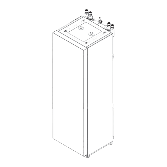
Page 45: Dimensional Drawings
Dimensional drawings Pos. Name Dim. Heating water outlet (feed) Ø 28 x 1 Heat source inlet (in heat pump) Ø 28 x 1 optionally at the top, on the right or left Empty conduit for electric/sensor cables Ø 35 x 1 Heating circuit safety valve Rp ¾"... - Page 46 Wall-mounting All dimensions in mm. Mounting on the unit All dimensions in mm. Subject to change without notice | 83056500qUK | ait-deutschland GmbH...
-
Page 47: Installation Plans
Installation plan 1 and 2 Keys: UK819445 All dimensions in mm. Version 1 Version 2 Free space for service purposes Free space for functionally necessary accessories Rh min. Minimum room height Subject to change without notice | 83056500qUK | ait-deutschland GmbH... - Page 48 Installation plan 3 Keys: UK819445 All dimensions in mm. Version 3 Free space for service purposes Rh min. Minimum room height Subject to change without notice | 83056500qUK | ait-deutschland GmbH...
-
Page 49: Hydraulic Integration
Default Subject to change without notice | 83056500qUK | ait-deutschland GmbH... - Page 50 Subject to change without notice | 83056500qUK | ait-deutschland GmbH...
Need help?
Do you have a question about the PWZS H1 Series and is the answer not in the manual?
Questions and answers
What is the Volume of water in the domestic water in the Water tank in an Alpha Innotec 12kwPWZSV122H1S Heat Pump
The volume of water in the domestic water tank of the Alpha-InnoTec PWZS H1 Series heat pump is 186 liters.
This answer is automatically generated