Table of Contents
Advertisement
Quick Links
AFE5801 8-Channel Variable Gain Amplifier (VGA) with
The AFE5801EVM is an evaluation tool designed for the ultrasound analog front-end (AFE) device
AFE5801. In order to deserialize the outputs of AFE5801, an ADSDeSer-50EVM or TSW1400EVM is
needed during the evaluation.
...................................................................................................................
1
1.1
1.2
1.3
1.4
2
2.1
2.2
2.3
2.4
3
3.1
3.2
3.3
3.4
4
4.1
4.2
4.3
5
1
2
3
4
5
6
7
................................................................................................................................
8
9
10
11
12
13
Clock Selection Jumper Configurations: (a) Transformer (default); (b) Single-ended Clock; (c) Future
Microsoft, Windows are registered trademarks of Microsoft Corporation.
SLOU257B - October 2009 - Revised March 2015
Submit Documentation Feedback
........................................................................................
..............................................................................................................
.....................................................................................................
.............................................................................................................
.........................................................................................................
.....................................................................................
........................................................................................
.................................................................................................
...........................................................................................................
.............................................................................................................
..............................................................................
...................................................................................................
....................................................................................................
......................................................................................................
..............................................................................
.........................................................................................................
........................................................................................................
....................................................................................................
.......................................................................................................
.............................................................................
List of Figures
..............................................................................................
...................................................................................................
.............................................................................................
..................................................................................................
....................................................................................
..............................................................................
.........................................................................................
AFE5801 8-Channel Variable Gain Amplifier (VGA) with Octal High-Speed
Copyright © 2009-2015, Texas Instruments Incorporated
SLOU257B - October 2009 - Revised March 2015
Octal High-Speed ADC
Contents
..............................................
.................................................
...........................................................................
.............................................................
...........................................................
User's Guide
3
3
3
3
3
5
5
6
6
9
9
9
14
14
15
16
16
22
30
32
33
45
4
5
5
7
8
9
10
10
11
12
13
14
1
ADC
Advertisement
Table of Contents

Related Manuals for Texas Instruments AFE5801


Summary of Contents for Texas Instruments AFE5801
-
Page 1: Table Of Contents
AFE5801 8-Channel Variable Gain Amplifier (VGA) with Octal High-Speed ADC The AFE5801EVM is an evaluation tool designed for the ultrasound analog front-end (AFE) device AFE5801. In order to deserialize the outputs of AFE5801, an ADSDeSer-50EVM or TSW1400EVM is needed during the evaluation. Contents ........................ - Page 2 Bottom Layer Signal ..................... Top Silk Screen Layer ....................Bottom Silk Screen Layer ........ Typical Performance of AFE5801. (a) Fixed Gain Mode; (b) Variable Gain Mode ..............Connection Between TSW1400EVM and AFE5801 .................... Connection of the Instruments ..................AFE5801EVM GUI - RUN Mode ..................
-
Page 3: Introduction
LED 1: U1 status indicator. Its ON state indicates the clock management chip U1 works well if U1 is installed. • LED 3 and 2 (RED): 1.8VD and 1.8VA power supply indicators. ON state indicates that the AFE5801 is powered correctly. •... -
Page 4: Afe5801Evm Led Locations
Introduction www.ti.com LED 2 LED 1 Figure 1. AFE5801EVM LED Locations AFE5801 8-Channel Variable Gain Amplifier (VGA) with Octal High-Speed SLOU257B – October 2009 – Revised March 2015 Submit Documentation Feedback Copyright © 2009–2015, Texas Instruments Incorporated... -
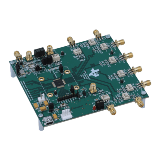
Page 5: Board Configuration
Ext Clk In Figure 2. AFE5801EVM TOP View AFE/TSW Adapter Connector Figure 3. AFE5801EVM BOTTOM View SLOU257B – October 2009 – Revised March 2015 AFE5801 8-Channel Variable Gain Amplifier (VGA) with Octal High-Speed Submit Documentation Feedback Copyright © 2009–2015, Texas Instruments Incorporated... -
Page 6: I/O And Power Connectors
P4’s connection. • External CLK Input (J9): ADC Clock input, such as FPGA outputs. FPGA outputs must be processed by U1. Otherwise, the ADC of AFE5801 will not achieve satisfactory performance. • +5V PWR connector(P10): Power supply input •... -
Page 7: Locations Of Jumpers, Headers And Switches On The Afe5801Evm
Board Configuration www.ti.com Figure 4. Locations of Jumpers, Headers and Switches on the AFE5801EVM SLOU257B – October 2009 – Revised March 2015 AFE5801 8-Channel Variable Gain Amplifier (VGA) with Octal High-Speed Submit Documentation Feedback Copyright © 2009–2015, Texas Instruments Incorporated... -
Page 8: Default Setup For Jumpers
Figure 5. Default Setup for Jumpers • P1: SPI interface for U1 • P2, P3: AFE5801 ADC clock input selection: transformer-based differential clock, single-ended LVCMOS clock, or future clock option (needs U1 to support). Default is to use transformer-based differential clock. •... -
Page 9: Test Points
This chapter describes how to operate the AFE5801EVM for evaluation. Both software and hardware installation and operation are discussed. Software Installation and Operation The AFE5801EVM comes with a software install. To Dowload the software, visit the AFE5801 product folder in the Tools & software section. Once the zip folder is downloaded, run setup.exe to install the software. -
Page 10: Found New Hardware Wizard (Next) Screen
Select "Search for the best driver in these locations" and enter the file path for ("C:\Program Files\AFE5801\CDM 2.04.06 WHQL Certified ") in the combo-box or browse to it by clicking the browse button. Once the file path has been entered in the box, click next to proceed. -
Page 11: Afe5801Evm Usb Spi Interface For General Registers
Several different screens appear displaying the different modes (Figure 9 through Figure Figure 9. AFE5801EVM USB SPI Interface for General Registers. SLOU257B – October 2009 – Revised March 2015 AFE5801 8-Channel Variable Gain Amplifier (VGA) with Octal High-Speed Submit Documentation Feedback Copyright © 2009–2015, Texas Instruments Incorporated... -
Page 12: Afe5801Evm Usb Spi Fixed Gain Mode
Board Operation www.ti.com Figure 10. AFE5801EVM USB SPI Fixed Gain Mode AFE5801 8-Channel Variable Gain Amplifier (VGA) with Octal High-Speed SLOU257B – October 2009 – Revised March 2015 Submit Documentation Feedback Copyright © 2009–2015, Texas Instruments Incorporated... -
Page 13: Afe5801Evm Usb Spi Interface For Variable Gain Mode
When AFE5801EVM is powered on, all registers have been set to their default modes. Refer to the datasheet for all default settings. It is recommended to restart the SPI software when AFE5801 is powered on in order to synchronize the AFE5801 register settings to the software displays. -
Page 14: Hardware Setup
SNR measurements of the AFE5801. Figure 12. Typical AFE5801 Bench Setup: The channel order of the AFE5801 outputs is not exactly the same as the one of ADS527x outputs. As a result, the channel number on the ADSDeSER-50EVM or AFE5801EVM might be misleading. -
Page 15: Data Analysis
AFE5801EVM). In this mode, the transform-based differential clock is used. Data Analysis Based on the data file acquired by a logic analyzer, the performance of AFE5801 can be evaluated. In Appendix A, we provide one solution (TI TSW1400 EVM) to analyze the data file using the PC. -
Page 16: Schematics, Layout, And, Bill Of Materials
This chapter provides the schematics and layout of the AFE5801EVM as well as the bill of materials. Schematics Figure 14. Schematic Page 1 AFE5801 8-Channel Variable Gain Amplifier (VGA) with Octal High-Speed SLOU257B – October 2009 – Revised March 2015 Submit Documentation Feedback... -
Page 17: Schematic
Schematics, Layout, and, Bill of Materials www.ti.com Figure 15. Schematic Page 2 SLOU257B – October 2009 – Revised March 2015 AFE5801 8-Channel Variable Gain Amplifier (VGA) with Octal High-Speed Submit Documentation Feedback Copyright © 2009–2015, Texas Instruments Incorporated... -
Page 18: Schematic
Schematics, Layout, and, Bill of Materials www.ti.com Figure 16. Schematic Page 3 AFE5801 8-Channel Variable Gain Amplifier (VGA) with Octal High-Speed SLOU257B – October 2009 – Revised March 2015 Submit Documentation Feedback Copyright © 2009–2015, Texas Instruments Incorporated... -
Page 19: Schematic
Schematics, Layout, and, Bill of Materials www.ti.com Figure 17. Schematic Page 4 SLOU257B – October 2009 – Revised March 2015 AFE5801 8-Channel Variable Gain Amplifier (VGA) with Octal High-Speed Submit Documentation Feedback Copyright © 2009–2015, Texas Instruments Incorporated... -
Page 20: Schematic
Schematics, Layout, and, Bill of Materials www.ti.com Figure 18. Schematic Page 5 AFE5801 8-Channel Variable Gain Amplifier (VGA) with Octal High-Speed SLOU257B – October 2009 – Revised March 2015 Submit Documentation Feedback Copyright © 2009–2015, Texas Instruments Incorporated... -
Page 21: Schematic
1.8 V per the AFE5801 data sheet, (SLOS591). Figure 19. Schematic Page 6 SLOU257B – October 2009 – Revised March 2015 AFE5801 8-Channel Variable Gain Amplifier (VGA) with Octal High-Speed Submit Documentation Feedback Copyright © 2009–2015, Texas Instruments Incorporated... -
Page 22: Pcb Layout
Top Silk Screen Layer • Bottom Silk Screen Layer Figure 20. Top Layer Signal AFE5801 8-Channel Variable Gain Amplifier (VGA) with Octal High-Speed SLOU257B – October 2009 – Revised March 2015 Submit Documentation Feedback Copyright © 2009–2015, Texas Instruments Incorporated... -
Page 23: Inner Layer 1 Ground
Schematics, Layout, and, Bill of Materials www.ti.com Figure 21. Inner Layer 1 Ground SLOU257B – October 2009 – Revised March 2015 AFE5801 8-Channel Variable Gain Amplifier (VGA) with Octal High-Speed Submit Documentation Feedback Copyright © 2009–2015, Texas Instruments Incorporated... -
Page 24: Inner Layer 2 Signal
Schematics, Layout, and, Bill of Materials www.ti.com Figure 22. Inner Layer 2 Signal AFE5801 8-Channel Variable Gain Amplifier (VGA) with Octal High-Speed SLOU257B – October 2009 – Revised March 2015 Submit Documentation Feedback Copyright © 2009–2015, Texas Instruments Incorporated... -
Page 25: Inner Layer 3 Power
Schematics, Layout, and, Bill of Materials www.ti.com Figure 23. Inner Layer 3 Power SLOU257B – October 2009 – Revised March 2015 AFE5801 8-Channel Variable Gain Amplifier (VGA) with Octal High-Speed Submit Documentation Feedback Copyright © 2009–2015, Texas Instruments Incorporated... -
Page 26: Inner Layer 4 Ground
Schematics, Layout, and, Bill of Materials www.ti.com Figure 24. Inner Layer 4 Ground AFE5801 8-Channel Variable Gain Amplifier (VGA) with Octal High-Speed SLOU257B – October 2009 – Revised March 2015 Submit Documentation Feedback Copyright © 2009–2015, Texas Instruments Incorporated... -
Page 27: Bottom Layer Signal
Schematics, Layout, and, Bill of Materials www.ti.com Figure 25. Bottom Layer Signal SLOU257B – October 2009 – Revised March 2015 AFE5801 8-Channel Variable Gain Amplifier (VGA) with Octal High-Speed Submit Documentation Feedback Copyright © 2009–2015, Texas Instruments Incorporated... -
Page 28: Top Silk Screen Layer
Schematics, Layout, and, Bill of Materials www.ti.com Figure 26. Top Silk Screen Layer AFE5801 8-Channel Variable Gain Amplifier (VGA) with Octal High-Speed SLOU257B – October 2009 – Revised March 2015 Submit Documentation Feedback Copyright © 2009–2015, Texas Instruments Incorporated... -
Page 29: Bottom Silk Screen Layer
Schematics, Layout, and, Bill of Materials www.ti.com Figure 27. Bottom Silk Screen Layer SLOU257B – October 2009 – Revised March 2015 AFE5801 8-Channel Variable Gain Amplifier (VGA) with Octal High-Speed Submit Documentation Feedback Copyright © 2009–2015, Texas Instruments Incorporated... -
Page 30: Bill Of Materials
LED, SMT, 0603, pure green, 2.03V Panasonic LNJ808R8ERA LED2, LED3 LED, SMT, 0603, orange, 1.8V AFE5801 8-Channel Variable Gain Amplifier (VGA) with Octal High-Speed SLOU257B – October 2009 – Revised March 2015 Submit Documentation Feedback Copyright © 2009–2015, Texas Instruments Incorporated... - Page 31 RF Transformer wideband, 0.03–125 MHz KFS2-M2.5 PEM NUTS UNINSTALLED 531220-2 P6, P9 SHUNT JUMPER 2POS SLOU257B – October 2009 – Revised March 2015 AFE5801 8-Channel Variable Gain Amplifier (VGA) with Octal High-Speed Submit Documentation Feedback Copyright © 2009–2015, Texas Instruments Incorporated...
-
Page 32: Typical Performance
A typical performance plot of the AFE5801 is shown in Figure 28 with 30dB digital gain setting. Figure 28. Typical Performance of AFE5801. (a) Fixed Gain Mode; (b) Variable Gain Mode AFE5801 8-Channel Variable Gain Amplifier (VGA) with Octal High-Speed SLOU257B – October 2009 – Revised March 2015 Submit Documentation Feedback Copyright ©... -
Page 33: Appendix Atsw1400 For Evaluating Afe5801
TSW1400 for Evaluating AFE5801 Introduction This application report goes through the steps of evaluating the AFE501 using the TSW1400EVM. Hardware Setup Figure 29. Connection Between TSW1400EVM and AFE5801 SLOU257B – October 2009 – Revised March 2015 TSW1400 for Evaluating AFE5801 Submit Documentation Feedback... -
Page 34: Connection Of The Instruments
Hardware Setup www.ti.com Figure 30. Connection of the Instruments Launch AFE5801 GUI From PC click Start Menu→All Programs→Texas Instruments→AFE5801EVM USB SPI→AFE5801EVM USB SPI The GUI may be running if the following screen appears: TSW1400 for Evaluating AFE5801 SLOU257B – October 2009 – Revised March 2015 Submit Documentation Feedback Copyright ©... -
Page 35: Afe5801Evm Gui - Run Mode
Figure 31. AFE5801EVM GUI - RUN Mode In case the GUI is not running, then press the START button of the GUI to run it. SLOU257B – October 2009 – Revised March 2015 TSW1400 for Evaluating AFE5801 Submit Documentation Feedback Copyright © 2009–2015, Texas Instruments Incorporated... -
Page 36: Afe5801 Evm Gui - Start Button
Hardware Setup www.ti.com Figure 32. AFE5801 EVM GUI - START Button • Commands to the AFE5801 GUI: 1. Click Init for TSW1400 to set the proper condition to work with TSW1400EVM. 2. Go to "TGC Register " Tab. 3. Press Variable button to change the mode to Fixed. -
Page 37: Afe5801Evm Gui - Variable Gain
Hardware Setup www.ti.com Figure 33. AFE5801EVM GUI - Variable Gain 4. Type 30 and press Write button. SLOU257B – October 2009 – Revised March 2015 TSW1400 for Evaluating AFE5801 Submit Documentation Feedback Copyright © 2009–2015, Texas Instruments Incorporated... -
Page 38: Afe5801Evm Gui - Setting Fixed Gain
Hardware Setup www.ti.com Figure 34. AFE5801EVM GUI - Setting Fixed Gain At this stage the AFE5801 is ready. Launch TSW1400 GUI • Graphics User Interface (GUI) TSW1400 provides a GUI for users to evaluate the performance of the device. When GUI is started, the screen of the following figure appears. -
Page 39: User Interface: Initial Setup Screen
• Test Condition Perform the steps in the order indicated in the following figure to set the test conditions: SLOU257B – October 2009 – Revised March 2015 TSW1400 for Evaluating AFE5801 Submit Documentation Feedback Copyright © 2009–2015, Texas Instruments Incorporated... -
Page 40: User Interface: Step-By-Step Setup
Hardware Setup www.ti.com Figure 36. User Interface: Step-by-Step Setup After completing the steps indicated, the following figure appears: TSW1400 for Evaluating AFE5801 SLOU257B – October 2009 – Revised March 2015 Submit Documentation Feedback Copyright © 2009–2015, Texas Instruments Incorporated... -
Page 41: User Interface: Frequency Load Value To Signal Generator
Set the Frequency of the Clock Generator to 40 MHz. Set the Amplitude of the Clock Generator to 13 dBm. SLOU257B – October 2009 – Revised March 2015 TSW1400 for Evaluating AFE5801 Submit Documentation Feedback Copyright © 2009–2015, Texas Instruments Incorporated... -
Page 42: User Interface: Final Setup Screen
Settings and inputs relevant to the test are entered in drop-down menus or text input boxes on the left portion of the window. TSW1400 for Evaluating AFE5801 SLOU257B – October 2009 – Revised March 2015 Submit Documentation Feedback Copyright © 2009–2015, Texas Instruments Incorporated... -
Page 43: User Interface: Single Fft Format
SLOU257B – October 2009 – Revised March 2015 TSW1400 for Evaluating AFE5801 Submit Documentation Feedback Copyright © 2009–2015, Texas Instruments Incorporated... -
Page 44: User Interface: Time Domain Format
The raw test sampled data can be saved to a file and processed by EXCEL or some other software. 4000 3500 3000 2500 2000 1500 1000 Figure 41. Plot of Saved Sample Data TSW1400 for Evaluating AFE5801 SLOU257B – October 2009 – Revised March 2015 Submit Documentation Feedback Copyright © 2009–2015, Texas Instruments Incorporated... -
Page 45: Appendix B High Speed Data Converter Pro (Hsdcpro) Gui Installation
Leave the destination directories as the default location, for the TSW1400GUI installation and press the NEXT button as shown in Figure SLOU257B – October 2009 – Revised March 2015 High Speed Data Converter Pro (HSDCPro) GUI Installation Submit Documentation Feedback Copyright © 2009–2015, Texas Instruments Incorporated... -
Page 46: Hsdcpro Install (Install Directory)
Appendix B www.ti.com Figure 43. HSDCPro Install (Install Directory) • Read the License Agreement from Texas Instruments and select I accept the License Agreement and press the Next button as shown in Figure High Speed Data Converter Pro (HSDCPro) GUI Installation SLOU257B –... -
Page 47: Hsdcpro Install (Ti License Agreement)
Read the License Agreement from National Instruments and select I accept the License Agreement and press the Next button as shown in Figure SLOU257B – October 2009 – Revised March 2015 High Speed Data Converter Pro (HSDCPro) GUI Installation Submit Documentation Feedback Copyright © 2009–2015, Texas Instruments Incorporated... -
Page 48: Hsdcpro Install (Ni License Agreement)
Figure 45. HSDCPro Install (NI License Agreement) • Press the Next button as shown in Figure High Speed Data Converter Pro (HSDCPro) GUI Installation SLOU257B – October 2009 – Revised March 2015 Submit Documentation Feedback Copyright © 2009–2015, Texas Instruments Incorporated... -
Page 49: Hsdcpro Install (Start Installation)
The window shown in Figure 47 should appear indicating that the installation is in progress. SLOU257B – October 2009 – Revised March 2015 High Speed Data Converter Pro (HSDCPro) GUI Installation Submit Documentation Feedback Copyright © 2009–2015, Texas Instruments Incorporated... -
Page 50: Hsdcpro Install (Installation Progress)
• The window shown in Figure 48 appears indicating Installation Complete. Press the Next button. High Speed Data Converter Pro (HSDCPro) GUI Installation SLOU257B – October 2009 – Revised March 2015 Submit Documentation Feedback Copyright © 2009–2015, Texas Instruments Incorporated... -
Page 51: Hsdcpro Install (Installation Complete)
Figure 48. HSDCPro Install (Installation Complete) • The window shown in Figure 49 appears briefly to complete the process. SLOU257B – October 2009 – Revised March 2015 High Speed Data Converter Pro (HSDCPro) GUI Installation Submit Documentation Feedback Copyright © 2009–2015, Texas Instruments Incorporated... -
Page 52: Hsdcpro Install (H)
National Instruments MCR Installer. If requested, hit the Restart button to complete the installation. Figure 50. HSDCPro Install High Speed Data Converter Pro (HSDCPro) GUI Installation SLOU257B – October 2009 – Revised March 2015 Submit Documentation Feedback Copyright © 2009–2015, Texas Instruments Incorporated... - Page 53 Added Appendix B: High Speed Data Converter Pro (HSDCPro) GUI Installation. NOTE: Page numbers for previous revisions may differ from page numbers in the current version. SLOU257B – October 2009 – Revised March 2015 Revision History Submit Documentation Feedback Copyright © 2009–2015, Texas Instruments Incorporated...
- Page 54 STANDARD TERMS AND CONDITIONS FOR EVALUATION MODULES Delivery: TI delivers TI evaluation boards, kits, or modules, including any accompanying demonstration software, components, or documentation (collectively, an “EVM” or “EVMs”) to the User (“User”) in accordance with the terms and conditions set forth herein. Acceptance of the EVM is expressly subject to the following terms and conditions.
- Page 55 FCC Interference Statement for Class B EVM devices NOTE: This equipment has been tested and found to comply with the limits for a Class B digital device, pursuant to part 15 of the FCC Rules. These limits are designed to provide reasonable protection against harmful interference in a residential installation.
- Page 56 【無線電波を送信する製品の開発キットをお使いになる際の注意事項】 本開発キットは技術基準適合証明を受けておりません。 本製品のご使用に際しては、電波法遵守のため、以下のいずれかの措置を取っていただく必要がありますのでご注意ください。 1. 電波法施行規則第6条第1項第1号に基づく平成18年3月28日総務省告示第173号で定められた電波暗室等の試験設備でご使用 いただく。 2. 実験局の免許を取得後ご使用いただく。 3. 技術基準適合証明を取得後ご使用いただく。 なお、本製品は、上記の「ご使用にあたっての注意」を譲渡先、移転先に通知しない限り、譲渡、移転できないものとします。 上記を遵守頂けない場合は、電波法の罰則が適用される可能性があることをご留意ください。 日本テキサス・インスツルメンツ株式会社 東京都新宿区西新宿6丁目24番1号 西新宿三井ビル 3.3.3 Notice for EVMs for Power Line Communication: Please see http://www.tij.co.jp/lsds/ti_ja/general/eStore/notice_02.page 電力線搬送波通信についての開発キットをお使いになる際の注意事項については、次のところをご覧くださ い。http://www.tij.co.jp/lsds/ti_ja/general/eStore/notice_02.page SPACER EVM Use Restrictions and Warnings: 4.1 EVMS ARE NOT FOR USE IN FUNCTIONAL SAFETY AND/OR SAFETY CRITICAL EVALUATIONS, INCLUDING BUT NOT LIMITED TO EVALUATIONS OF LIFE SUPPORT APPLICATIONS.
- Page 57 Notwithstanding the foregoing, any judgment may be enforced in any United States or foreign court, and TI may seek injunctive relief in any United States or foreign court. Mailing Address: Texas Instruments, Post Office Box 655303, Dallas, Texas 75265 Copyright © 2015, Texas Instruments Incorporated...
- Page 58 IMPORTANT NOTICE Texas Instruments Incorporated and its subsidiaries (TI) reserve the right to make corrections, enhancements, improvements and other changes to its semiconductor products and services per JESD46, latest issue, and to discontinue any product or service per JESD48, latest issue.
- Page 59 Mouser Electronics Authorized Distributor Click to View Pricing, Inventory, Delivery & Lifecycle Information: Texas Instruments AFE5801EVM...
Need help?
Do you have a question about the AFE5801 and is the answer not in the manual?
Questions and answers