Page 1
Product Registration QR code is located on the front of your appliance. 2. Tap the notification or link to open the registration from 3. Complete you rdetails and enjoy peace of mind
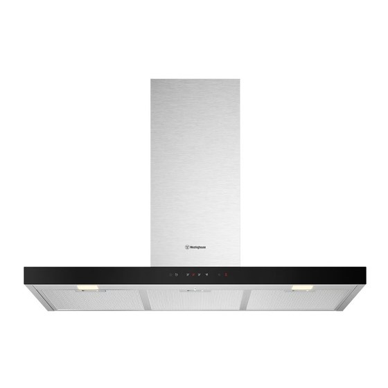
 CANOPY RANGEHOOD CANOPY RANGEHOOD WRC924SD WRC924SD WRC924DSD WRC924DSD...
Record model and serial number here: ability to make a claim under the Westinghouse manufacturer’s warranty Model number:.............. provided with your product. Products Serial number: ............... must be used, installed and operated in accordance with this manual.
SAFETY INSTRUCTIONS This manual explains the proper use of your new Westinghouse canopy rangehood. Please read this manual carefully before using the product. This manual should be kept in a safe place for handy reference. This canopy rangehood is a domestic appliance which has been manufactured and tested to comply with Australian and New Zealand Standard AS/NZS 60335.1 and AS/NZS 60335.2.31.
Page 4
• Always cover lit gas burners with pots or pans when canopy rangehood is in use. • Always switch off gas burners before you remove pots or pans. • Do not leave lit gas burners exposed due to the risk of fire.(Fig 2) •...
Duct transition Non-return flap Carbon filter Machine Warning Failure to install the screws or fixing device in accordance these instructions may result in electrical hazards. ACCESSORY LIST USER MANUAL 550 (max) CANOPY RANGEHOOD WRC924SD WRC924DSD *These accessories are supplied with product...
INSTALLATION Before installing the cooker hood, peel off any protective plastic covering. DIMENSIONS ARE IN MILLIMETRES Note If the instructions of the hob specify a greater distance than the minimum, then that shall be the minimum height for the installation Hood Base Minimum 600 Electric...
Page 7
Recommended installation mode For External exhaust mode installation • Type ① is recommended when the distance from the ceiling to the bottom of the hood is < 950 mm. • Type ② is recommended when the distance from the ceiling to the bottom of the hood is ≥...
Page 8
Recommended installation sequence External exhaust mode installation WOOD SCREWS Ø4*30 WALL PLUG * Leave 3mm gap between Take the ring off before installing, it screw head and wall is for transportation only and may be disposed of. Diagram C1 • Install cooker hood body. Determine working height, mark wall to suit. Install flue cover mounting brackets.
Page 9
Power box Flue Hose clamp Duct transition Diagram G1 ST 4.2*12mm ST 3.2*13mm • Insert the clip of power box into product Diagram H1 • Fasten the power box with the screws supplied to ensure the power box is securely fastened. Diagram I1 •...
Page 10
Recommended installation sequence Recirculation mode installation WOOD SCREWS Ø4*30 WALL PLUG * Leave 3mm gap between screw head and wall Take the ring off before installing, it is for transportation only and may be disposed of. Diagram C2 • Install cooker hood body. Determine working height, mark wall to suit. Install flue cover mounting brackets.
Page 11
Power box ST 3.2*13mm ST 4.2*12mm Diagram H2 Diagram G2 • Fasten the power box with the screws • Insert the clip of power box into product supplied to ensure the power box is securely fastened S T 4 . 2 * 6 . 5 m m I2-2 I2-1 Diagram I2-1...
Page 12
Flue Hose clamp Duct transition Diagram K2 • Install Carbon filter Diagram L2 • Loosen the hose clamp and put it outside of Duct transition • Fit the flue over the outer wall of Duct transition • Tighten the hose clamp with a screwdriver to secure to Duct transition. Plastic diverter Hose...
PRODUCT DESCRIPTION Control panel overview On/Off PowerBoost Delay Off Light Fan Speed 1 Hob2Hood Fan Speed 2 Filter Notification Fan Speed 3 DAILY USE Use the hood Check the recommended speed according to the table below After cooking, The hood will continue to run next 5minutes before shutting down automatically to remove residual fumes or water vapour.
Page 14
Activate and deactivate Delay Off Hob2Hood* When activated, the icon will start * It is an automatic function which flashing and the hood will continue to run connects the hob with a hood. Both the for the next five minutes before shutting hob and the hood have an infrared signal down automatically.
Page 15
Activate and deactivate the Flter Filter Alarms Notification The filter alarm is a Notification to change the Carbon filter and clean the grease Switch on the control panel. Make sure that the Fan Speed is filter. The filter indicator is turned on turned off.
CARE AND CLEANING 1. Remove the grease filters from the Clean the grease filter appliance to access the Carbon filter. Each filter must be cleaned at least once a Refer to “Cleaning the grease filter” in this month. Filter are mounted with the use of chapter.
Page 17
Note This product is fitted with a safety cutout device. The cutout device may activate if follow occurs; • Hood installed too close to cooktop • Flambe cooking • Operation of the cooktop without utensils covering burners hot plates • Blocked filters.
This document sets out the terms and conditions of the (a) light globes, batteries, filters or similar perishable parts; product warranties for Westinghouse Appliances. It is an (b) parts and Appliances not supplied by Electrolux; important document. Please keep it with your proof of...