Advertisement
Quick Links
USER MANUAL
USER MANUAL
Enjoy peace of mind.
Register your appliance today.
Stay updated on better living services, safety notices and
shop for accessories.
1. Open the camera app on your smartphone and
point at the QR code to scan
Product Registration QR code is located on the
front of your appliance.
2. Tap the notification or link to open the registration from
3. Complete you rdetails and enjoy peace of mind
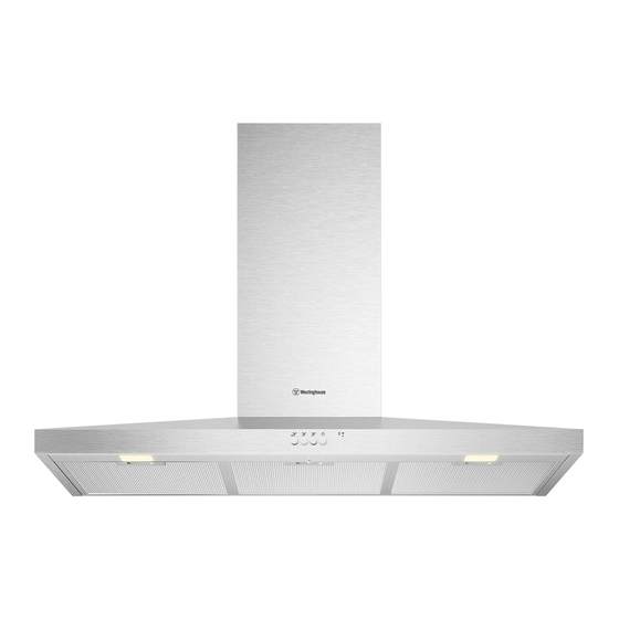
CANOPY RANGEHOOD
WRC914SD
CANOPY RANGEHOOD
WRC614SD
WRC914SD
WRC614SD
Advertisement

Subscribe to Our Youtube Channel
Related Manuals for Westinghouse WRC914SD


Summary of Contents for Westinghouse WRC914SD
- Page 1 Product Registration QR code is located on the front of your appliance. 2. Tap the notification or link to open the registration from 3. Complete you rdetails and enjoy peace of mind CANOPY RANGEHOOD WRC914SD CANOPY RANGEHOOD WRC614SD WRC914SD WRC614SD...
-
Page 2: Table Of Contents
Record model and serial number here: ability to make a claim under the Westinghouse manufacturer’s warranty Model number:.............. provided with your product. Products Serial number: ............... must be used, installed and operated in accordance with this manual. -
Page 3: Safety Instructions
SAFETY INSTRUCTIONS This manual explains the proper use of your new Westinghouse canopy rangehood. Please read this manual carefully before using the product. This manual should be kept in a safe place for handy reference. This canopy rangehood is a domestic appliance which has been manufactured and tested to comply with Australian and New Zealand Standard AS/NZS 60335.1 and AS/NZS 60335.2.31. - Page 4 • Always cover lit gas burners with pots or pans when canopy rangehood is in use. • Always switch off gas burners before you remove pots or pans. • Do not leave lit gas burners exposed due to the risk of fire.(Fig 2) •...
-
Page 5: Accessory List
Non-return flap Carbon filter Machine Warning Failure to install the screws or fixing device in accordance these instructions may result in electrical hazards. ACCESSORY LIST USER MANUAL 550 (max) CANOPY RANGEHOOD WRC914SD WRC614SD *These accessories are supplied with product 598/898... -
Page 6: Installation
INSTALLATION Before installing the cooker hood, peel off any protective plastic covering. DIMENSIONS ARE IN MILLIMETRES Note If the instructions of the hob specify a greater distance than the minimum, then that shall be the minimum height for the installation Hood Base Maximum 800 mm... - Page 7 Recommended installation mode For External exhaust mode installation • Type ① is recommended when the distance from the ceiling to the bottom of the hood is < 900 mm. • Type ② is recommended when the distance from the ceiling to the bottom of the hood is ≥...
- Page 8 Recommended installation sequence External exhaust mode installation WOOD SCREWS Ø4*30 WALL PLUG Ø6 * Leave 3mm gap between screw head and wall Take the ring off before installing, it is for transportation only and may be disposed of. Diagram C1 •...
- Page 9 Power box Flue Hose clamp Duct transition Diagram G1 ST 3.2*13mm ST 4.2*12mm • Insert the clip of power box into product Diagram H1 • Fasten the power box with the screws supplied to ensure the power box is securely fastened. Diagram I1 •...
- Page 10 Recommended installation sequence Recirculation mode installation WOOD SCREWS Ø4*30 WALL PLUG * Leave 3mm gap between Take the ring off before installing, it screw head and wall is for transportation only and may be disposed of. Diagram C2 • Install cooker hood body. Determine working height, mark wall to suit. Install flue cover mounting brackets.
- Page 11 Power box ST 3.2*13mm ST 4.2*12mm Diagram G2 • Insert the clip of power box into product ST 4.2*6.5mm I2-2 I2-1 Diagram I2-1 Diagram I2-2 • First loosen the seven screws shown in • Fasten the adaptors for plastic frame the figure.
- Page 12 Flue Hose clamp Duct transition Diagram K2 Diagram H2 • Install Carbon filter • Fasten the power box with the screws supplied to ensure the power box is securely fastened Diagram L2 • Loosen the hose clamp and put it outside of Duct transition •...
-
Page 13: Product Description
PRODUCT DESCRIPTION Control panel overview Fan Speed 1 /Off Hob2Hood Indicator Fan Speed 2 Filter Notification Indicator Fan Speed 3 Light DAILY USE Use the hood Check the recommended speed according to the table below While heating up food, cooking with covered pots, light frying, light boiling. While cooking with covered pots on multiple cooking zones or burners, frying, boiling. - Page 14 Activate and deactivate the Hob2Hood* filter notification * It is an automatic function which connects the hob with a hood. Both the hob and the hood have an infrared signal Switch on the control panel. communicator. Speed of the fan is defined Make sure that the Fan Speed is automatically on basis of mode setting turned off.
- Page 15 Activate and deactivate the Filter alarm Reset Sound Profile To activate or deactivate the Sound Profile Refer to activating and deactivating the press button 'Light' for 2 seconds. The filter alarm in daily use chapter. 'Light' flashes(white) once if sounds are enabled and twice if sounds are disabled.
-
Page 16: Care And Cleaning
CARE AND CLEANING The time of saturation of the carbon filter Clean the grease filter varies depending on th type of cooking Each filter must be cleaned at lease once a and the regularity of cleaning the grease month. Filter are mounted with the use of filter. - Page 17 Note This product is fitted with a safety cutout device. The cutout device may activate if follow occurs; • Hood installed too close to cooktop • Flambe cooking • Operation of the cooktop without utensils covering burners hot plates • Blocked filters.
- Page 18 NOTE...
-
Page 19: Warranty
This document sets out the terms and conditions of the (a) light globes, batteries, filters or similar perishable parts; product warranties for Westinghouse Appliances. It is an (b) parts and Appliances not supplied by Electrolux; important document. Please keep it with your proof of... - Page 20 0800 10 66 10 email: customercare@electrolux.co.nz web: westinghouse.co.nz and WESTINGHOUSE are trademarks of Westinghouse Electric Corporation. Used under license by Electrolux Home Products Pty Ltd. All Rights Reserved. © 2023 Electrolux Home Products Pty Ltd. ABN 51 004 762 341 WMAN_Pyramid_Nov2023...
Need help?
Do you have a question about the WRC914SD and is the answer not in the manual?
Questions and answers