Table of Contents
Advertisement
Available languages
Available languages
Quick Links
π
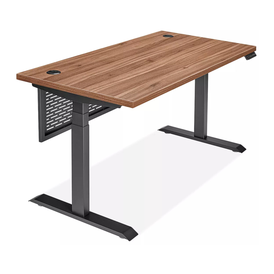
H-11111, H-11112
METRO COLLECTION –
ADJUSTABLE HEIGHT DESK
TOOLS NEEDED
Phillips
4 mm Allen Wrench
Screwdriver
(included)
1
5
4
3
NOTE: Count and inspect all pieces before
disposing of any carton or packing materials.
• Install bolts using 4 mm Allen wrench.
• Install screws using Phillips screwdriver.
CAUTION! Adjustable frame is heavy and
care should be used when moving it during
assembly.
PAGE 1 OF 21
1-800-295-5510
uline.com
Two Person Assembly
Recommended
PARTS
5
2
6
9
7
4
3
8
Pour le français, consulter les pages 15-21.
PARTS
#
DESCRIPTION
1
Desktop
2
Metal Modesty Panel
3
Foot with Leveling Glides
4
Lifting Column
5
Top Support Bracket
6
Center Frame
7
Control Box
8
Cable Management Tray
9
Programmable Handset
Hardware Kit
A
B
Grommet
Modesty Panel
Cap x 2
Bracket x 2
D
E
M6 x 40 mm
M6 x 10 mm Bolt
Bolt x 8
(20 for H-11111)
(16 for H-11112)
G
H
ST5 x 16 mm
ST3.5 x 16 mm
Screw x 2
Screw x 5
J
Extension Wire x 1
Para Español, vea páginas 8-14.
QTY.
1
1
2
2
2
1
1
1
1
C
Modesty Panel
Connector x 2
F
M6 x 14 mm
Bolt x 23
I
Cable
Clip x 5
K
Power Cord x 1
1123 IH-11111
Advertisement
Table of Contents

Subscribe to Our Youtube Channel
Related Manuals for U-Line H-11111


Summary of Contents for U-Line H-11111
- Page 1 M6 x 10 mm Bolt M6 x 14 mm NOTE: Count and inspect all pieces before Bolt x 8 (20 for H-11111) Bolt x 23 (16 for H-11112) disposing of any carton or packing materials. • Install bolts using 4 mm Allen wrench.
- Page 2 ASSEMBLY Place one lifting column (4) upside down on a 3. Insert top support bracket (5) into the outside of smooth, non-marring surface. Attach lifting column the center frame (6). Install using two M6 x 10 mm to center frame (6) using four M6 x 10 mm bolts (E). bolts (E).
- Page 3 ASSEMBLY CONTINUED Determine whether to install programmable NOTE: One of the pre-installed lifting column handset (9) in pilot holes located on the left or right cables will not reach control box (7). Use the side of the desktop (1). In desired location, align extension wire (J) to connect lifting column with pilot holes and install using two ST5 x 16 mm cable to control box.
- Page 4 ASSEMBLY CONTINUED 10. Align holes on modesty panel brackets (B) with holes 13. Desk is now fully assembled. Using two people, on outer edge of metal modesty panel (2). Attach carefully flip the desk onto the feet. using two M6 x 14 mm bolts (F). Repeat on opposite 14.
-
Page 5: Operation
OPERATION Display Down Four Preset Setting Button Button Position Buttons Button Charger 2 3 4 1 2 3 4 M CAUTION! Ensure there are no obstacles in the desk's height adjustment path, and ensure the desk is not touching any walls. CAUTION! Ensure all cords are at the appropriate length to accommodate changes in height. -
Page 6: Troubleshooting
OPERATION CONTINUED LOCKING OPERATION • To lock the desk, press the "M" button to display " ". Hold the "M" button for 10 seconds until " " is displayed. • To unlock the desk, press and hold the "M" button for 10 seconds while " "... - Page 7 TROUBLESHOOTING CONTINUED OPERATING ISSUE RECOMMENDATIONS Desk does not go up or down, but handset Faulty height limits may be programmed and displays digits that are flashing. should be canceled. Press the "M" setting button to display " " on the handset. Press and hold the "M"...
-
Page 8: Herramientas Necesarias
Pernos M6 x 10 mm 23 Pernos NOTE: Count and inspect all pieces before M6 x 40 mm (20 para H-11111) M6 x 14 mm (16 para H-11112) disposing of any carton or packing materials. • Install bolts using 4 mm Allen wrench. - Page 9 ENSAMBLE 1. Voltee la columna de elevación (4) y colóquela 3. Inserte el soporte superior (5) en la parte exterior del sobre una superficie lisa que no deje marcas. Fije armazón central (6). Instale con dos pernos la columna de elevación al armazón central (6) M6 x 10 mm (E).
- Page 10 CONTINUACIÓN DEL ENSAMBLE Determine si instalará el control manual NOTA: Uno de los cables de las columnas de programable (9) en los orificios guía localizados en elevación preinstalados no alcanzará la caja el lado izquierdo o derecho de la cubierta (1). En la de control (7).
- Page 11 CONTINUACIÓN DEL ENSAMBLE 10. Alinee los orificios en los soportes para recato (B) 13. El escritorio ahora está completamente con los orificios en el borde exterior del recato de ensamblado. Entre dos personas, enderece el metal (2). Fije utilizando dos pernos M6 x 14 mm (F). escritorio con cuidado y póngalo de pie.
-
Page 12: Ajuste De Altura
FUNCIONAMIENTO Pantalla Botón Botón Cuatro Botones de Posiciones Botón de Cargador Arriba Abajo Preprogramadas Ajuste 2 3 4 1 2 3 4 M ¡PRECAUCIÓN! Asegúrese de que no haya obstáculos en la trayectoria de la altura ajustable del escritorio y asegúrese de que no esté tocando ninguna pared. ¡PRECAUCIÓN! Asegúrese de que el largo de los cables se encuentre de tal manera que permita los cambios de altura. -
Page 13: Solución De Problemas
CONTINUACIÓN DE FUNCIONAMIENTO OPERACIÓN DE BLOQUEO • Para bloquear el escritorio, presione el botón de ajuste "M" para mostrar " ". Sostenga el botón "M" durante 10 segundos hasta que la pantalla muestre " ". • Para desbloquear el escritorio, presione y sostenga el botón "M" durante 10 segundos mientras la pantalla muestra "... - Page 14 CONTINUACIÓN DE SOLUCIÓN DE PROBLEMAS PROBLEMA DE FUNCIONAMIENTO RECOMENDACIONES El escritorio no sube ni baja, pero el control Los límites de altura podrían estar mal programados y se manual muestra dígitos que parpadean. deben cancelar. Presione el botón de ajuste "M" para mostrar "...
-
Page 15: Outils Requis
Boulon Boulon M6 x 10 mm Boulon REMARQUE : Comptez et vérifiez toutes les M6 x 40 mm x 8 (20 pour H-11111) M6 x 14 mm x 23 (16 pour H-11112) pièces avant de jeter le matériel d'emballage ou le carton. • Installez les boulons avec la clé Allen de 4 mm. -
Page 16: Montage
MONTAGE Placez une colonne de levage (4) à l'envers sur une 3. Insérez une ferrure de support de la surface (5) surface lisse qui ne marque pas. Fixez la colonne dans la partie extérieure du cadre central (6). de levage au cadre central (6) avec quatre boulons Fixez-la avec deux boulons M6 x 10 mm (E). - Page 17 MONTAGE SUITE Déterminez si le contrôleur programmable (9) sera REMARQUE : Un des câbles pré-installés sur les installé dans les avant-trous sur le côté gauche ou colonnes de levage ne pourra pas atteindre droit de la surface de bureau (1). À l'emplacement le boîtier de commande (7).
- Page 18 MONTAGE SUITE 10. Alignez les trous des supports de panneau cache- 13. Le montage du bureau est maintenant complété. À jambes (B) sur les trous situés sur le bord extérieur du deux, placez le bureau avec soin à l'endroit. panneau cache-jambes en métal (2). Fixez-les avec 14.
-
Page 19: Réglage De La Hauteur
FONCTIONNEMENT Affichage Touche Touche Quatre touches de position Touche de Chargeur haut préréglée réglage 2 3 4 2 3 4 M MISE EN GARDE! Assurez-vous que le bureau ne touche aucun mur et qu'aucun obstacle n'entrave son mouvement. MISE EN GARDE! Assurez-vous que tous les cordons ont une longueur appropriée convenant au changement de hauteur. -
Page 20: Blocage Du Fonctionnement
FONCTIONNEMENT SUITE BLOCAGE DU FONCTIONNEMENT • Pour bloquer le bureau, appuyez sur la touche « M » pour afficher « ». Appuyez longuement sur la touche « M » pendant 10 secondes jusqu'à ce que « » s'affiche. • Pour débloquer le bureau, appuyez longuement sur la touche « M » pendant 10 secondes jusqu'à ce que « LOC »... - Page 21 DÉPANNAGE SUITE PROBLÈME RECOMMANDATIONS Le bureau ne monte ni ne descend, mais le Des limites de hauteur erronées peuvent être contrôleur affiche des chiffres qui clignotent. programmées et doivent être annulées. Appuyez sur la touche de réglage « M » pour afficher « ...
Need help?
Do you have a question about the H-11111 and is the answer not in the manual?
Questions and answers