Table of Contents
Advertisement
Quick Links
Advertisement
Table of Contents

Related Manuals for Geco GC207


Summary of Contents for Geco GC207
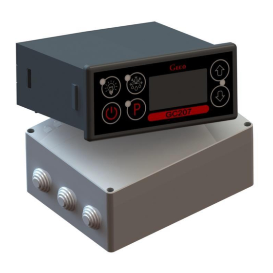
- Page 1 INSTALLATION, OPERATING AND MAINTENANCE MANUAL GC207 COOLING APPLIANCES CONTROLLER For software version 02 Please, read the manual very carefully before connecting and starting any of our devices. In case of doubt please contact our company between 8am and 4pm.
-
Page 2: Table Of Contents
Contents: GENERAL FEATURES ........................... 3 MARKING AND SPECIFICATIONS ..................... 3 III. HOW TO ORDER ............................ 4 DELIVERY, INSTALLATION AND CONNECTION ................4 INSTALLATION OF SENSORS, TYPES OF COVER SHELLS ............5 GENERAL OPERATION PRINCIPLES ....................6 General Information ..........................6 Defrosting ............................... -
Page 3: General Features
The Controller is a microprocessor-based device manufactured using Surface Mount Technology (SMT). Thanks to the two-piece housing and innovative technical solutions, GC207 can be used in any piece of furniture and in a simple cold room. Operating under a safe 5V voltage, the control panel can be mounted anywhere, without the need for cutting additional holes and guiding many power supply cables far from the controlled appliances. -
Page 4: How To Order
2. The executive module should be placed on the rail and locked with a latch. In the case of store devices, it is REQUIRED to mount the SBR executive module with the mounting strip facing down!!! 3. Any metal elements through which the GC207 or its cables are passed should be filed down or otherwise secured. Page 4 3rd edition AS FROM 01.12.2017... -
Page 5: Installation Of Sensors, Types Of Cover Shells
THE SAME CONDITION APPLIES TO ANY OTHER REPAIRS!!! 9. If heaters are used, their power must be selected so that in the event of a failure of the GC207 or the contactor and switching them on permanently, there is no possibility of fire or destruction of the device. -
Page 6: General Operation Principles
8. Every time the temperature setting is reached (the user temperature setting plus the upper hysteresis value) and after every power outage or drop below 175V, the GC207 allows to re-activate the compressor for the time determined by the 'c2' parameter. However, if the 'c2' = 0min, then the protection after power outage continues for 60 seconds. -
Page 7: Defrosting
3. If defrosting occurs and the temperature on the evaporator is lower than the value set in the 'd2' parameter, the GC207 will start defrosting and after reaching the temperature specified in the 'd2' parameter, it will enter the defrosting exit procedure (this state is signalled by the blinking of the... -
Page 8: Principle Of Operation Of The Door Opening Sensor
C. Principle of operation of the door opening sensor 1. If the door is opened, the fan stops immediately and in GC207, depending on the setting of the 'r7' parameter, the light may be turned on. The temperature reading is shown in the display. -
Page 9: On/Off Diagrams For Individual Assemblies Of The Appliance
VII. ON/OFF DIAGRAMS FOR INDIVIDUAL ASSEMBLIES OF THE APPLIANCE A thick line means switching on, and a dashed line means switching off individual devices. Defrosting exit consists of two phases – see chapter V p.3. The “Downtime” field means switching off, and “Work” – switching on of the compressor due to exceeding the programmed temperature, of course, taking into account the value of the programmed hysteresis, parameter 'd3'. -
Page 10: Setting The System Parameters
VIII. SETTING THE SYSTEM PARAMETERS Once the device is started and checked for proper operation (default settings are factory set) you can begin to enter the system parameters of the GC207. To do this, turn off the device with the button. - Page 11 – the parameter does not work when defrosting Setting the parameter to +40°C disables this control. Mode of fan operation during defrosting 00 – 'classic' mode according to the Geco algorithm 01 – always on during defrosting 02 – always off during defrosting...
-
Page 12: Troubleshooting
- the presence of 220V voltage on the L and N power terminals not light up even - correct connection of the executive module with the control panel though the GC207 - pull out and insert the ribbon slots - connect another ribbon... - Page 13 - presence of 220V voltage on terminals K and N – if present, check 2. The compressor does not turn on the compressor despite signalling its - if not, check the correct connection of the executive module with the activation control panel red diode - check the jumper powering relay P5...
-
Page 14: Returning For Repair
PPUH GECO reserves the right to refuse to accept the device for free repair if the seals are found to be broken!!! P.P.U.H. Geco Sp. z o.o. is not liable for losses and damage resulting from the fact that the manufacturer of the refrigeration device or its service provided the... - Page 15 THE PICTURE SHOWS A VIEW OF THE PLUGS FROM THE SIDE OF THE HOLES THEIR RELATION EACH OTHER AND THE SELECTED RIBBON STRIP, AFTER CORRECT CONNECTION!!! Page 15 3rd edition AS FROM 01.12.2017...
-
Page 16: Block Diagram Of The Standard Version Of The Actuator Module
XII. BLOCK DIAGRAM OF THE STANDARD VERSION OF THE ACTUATOR MODULE Power supply 1* – version with a mechanical door opening sensor 2* – version with optical door opening sensor CONTROL Model: Un = 230V 50Hz lmax = 10A 1- COMPRESSOR1 8A 2HP 1500W G-207-M12345Y-P00 2- LIGHT 4A 750W 3- FAN 4A 1HP 750W... -
Page 17: Block Diagram In The Extended Version Of The Executive Module
XIII. BLOCK DIAGRAM IN THE EXTENDED VERSION OF THE EXECUTIVE MODULE 1* – version with a mechanical door opening sensor 2* – version with optical door opening sensor Model: Un = 230V 50Hz lmax=10A G-207-M12345Y-P00 1 -COMPRESSOR1 8A 2HP 1500W 2 –...
Need help?
Do you have a question about the GC207 and is the answer not in the manual?
Questions and answers