Table of Contents
Advertisement
Quick Links
Advertisement
Table of Contents

Related Manuals for Geco GC202


Summary of Contents for Geco GC202
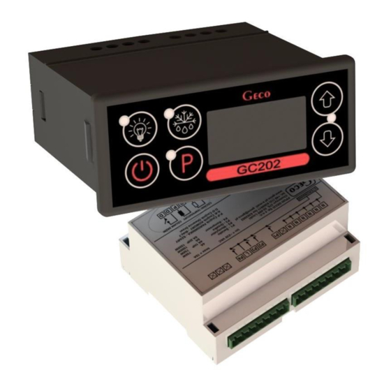
- Page 1 INSTALLATION, OPERATING AND MAINTENANCE MANUAL GC202 COOLING APPLIANCES CONTROLLER For software version 01 Please read the manual very carefully before connecting and starting any of our devices. In case of doubt, please contact our company between 8am and 4pm.
-
Page 2: Table Of Contents
CONTENTS GENERAL CHARACTERISTICS ........................3 MARKING AND SPECIFICATIONS ........................3 HOW TO ORDER ................................4 III. DELIVERY, INSTALLATION AND CONNECTION ..................... 5 PRINCIPLE OF SENSOR ASSEMBLY, TYPES OF COVER SHELLS ..............6 MODE OF OPERATION..............................6 A – G ENERAL INFORMATION ........................................B –... -
Page 3: General Characteristics
Controller is a microprocessor-based device manufactured using Surface Mount Technology (SMT). Thanks to the two-piece housing, the GC202 can be used for any piece of furniture and a simple cold room. Operating under a safe 12V voltage, the control panel can be mounted anywhere, without need for cutting additional holes and guiding many power-supply cables far from the controlled appliances. -
Page 4: How To Order
10A!!! III. ORDERING INFORMATION The order should specify: 1. Full name of the controller, e.g. GC202.02 2. Length of the ribbon connecting the executive module and the keypad panel (the standard length of the ribbon is 1m). 3. Length of temperature sensors (standard sensor lengths are 2.5m and 3.0m). -
Page 5: Delivery, Installation And Connection
THE SAME CONDITION APPLIES TO ANY OTHER REPAIRS!!! 9. If heaters are used, their power must be selected so that in the event of a failure of the GC202 or the contactor and switching them on permanently, there is no possibility of fire or destruction of the device. -
Page 6: Principle Of Sensor Assembly, Types Of Cover Shells
V. INSTALLATION OF SENSORS, TYPES OF COVER SHELLS 1. For each type of manufactured device, the place of mounting the chamber and evaporator sensor, as well as the SBR setting should be selected experimentally. It is absolutely forbidden to change the place or method of mounting the sensors and SBR settings without conducting new tests regarding temperature stabilisation and defrosting of the device!!! 2. - Page 7 To enable the evaporator temperature preview, hold the button longer, then the display will start flashing and indicate the reading. After 5 seconds, the GC202 will automatically return to reading the temperature of the chamber or the additional temperature sensor.
-
Page 8: B - Defrosting
A1 – Damage to the chamber temperature sensor. GC202 will turn on the compressor in a time cycle (so-called timer control) according to the times specified in the 'c08' and 'c09’ parameters. -
Page 9: C - Principle Of Operation Of The Door Opening Sensor
C – Door opening sensor operating principle 1. If the door is opened, the fan stops immediately and in GC202, depending on the setting of the 'r7' parameter, the light may be turned on. The temperature reading is shown in the display. If the... -
Page 10: D - Hysteresis
If the parameter is r6=01, the sensor is closed when the door is opened, while if the parameter is r6=02, the sensor is open when the door is opened. D – HYSTERESIS When programming the 'd0' and 'd1' parameters (the minimum and maximum temperature that can be set by the customer), remember that the 'd3' hysteresis value causes an additional 'pull' of the temperature down and up from the temperature set by the user. - Page 11 The heater on “diagram 1” is for heating the tray and/or the evaporator water drain hose, and the heater on “diagram 5” is for heating the evaporator water drain hose only. ERROR IN PARAMETERS SETTING WILL RESULT IN WRONG OPERATION OF THE DEVICE!!! The first 6 graphs refer to setting the parameter 'r0' = 00 –...
-
Page 12: Setting The System Parameters
VIII. SETTING THE SYSTEM PARAMETERS Once the device is started and checked for proper operation (default settings are factory set) you can begin to enter the system parameters of the GC202. To do this, turn off the device with the button (three horizontal lines will appear on the display). - Page 13 If no button is pressed within 20 seconds, the device will exit the parameter programming mode. ATTENTION !!! Incorrect change of parameter settings may cause faulty operation of the device!!! Table 2: Designation of parameters Para Min. Max Step Factory cript setting C00 How often defrosting should take place Attention!!! If this...
- Page 14 Mode of fan operation during defrosting 00 – works according to the diagrams in chapter VII 01 – always on during defrosting 02 – always off during defrosting Determining the defrosting method of the evaporator, the parameter is set to: 01 –...
-
Page 15: Troubleshooting
- the presence of 230V voltage on the L and N power terminals light up even though - correct connection of the executive module with the control panel the GC202 is - pull out and insert the ribbon slots connected to the mains - connect another ribbon - presence of 230V voltage on terminals K and N –... -
Page 16: Returns For Repair
PPUH GECO reserves the right to refuse to accept the device for free repair if the seals are found to be broken!!! P.P.U.H. Geco Sp. z o.o. is not liable for losses and damage resulting from the fact that the manufacturer of the refrigeration device or its service... -
Page 17: Diagram Of Connection Of Devices To The Controller
XI. DIAGRAM OF CONNECTION OF DEVICES TO THE CONTROLLER Power supply 1* – version with a mechanical door opening sensor: GC202.01, GC202.02 2* – version with optical door opening sensor: GC202.03 Door sensor: 1 – OUT – black 2 – GND – blue (previously white) 3 –... -
Page 18: Equipment
XII. INFORMATION ON MARKING AND COLLECTING WASTE ELECTRICAL AND ELECTRONIC EQUIPMENT ATTENTION! The symbol placed on a product or on its packaging indicates that it is subject to selective collection of waste electric and electronic equipment. This means that the product should not be discarded with other household waste. - Page 19 P.P.U.H. Geco Sp. z o.o. Cholerzyn 376, 32-060 Liszki, Poland phone: +48 12 6369811, 6361290 fax: +48 12 6362002 http://www.geco.pl e-mail: geco@geco.pl...
Need help?
Do you have a question about the GC202 and is the answer not in the manual?
Questions and answers