Table of Contents
Advertisement
Quick Links
SERVICE MANUAL FOR THE CONTROLLER
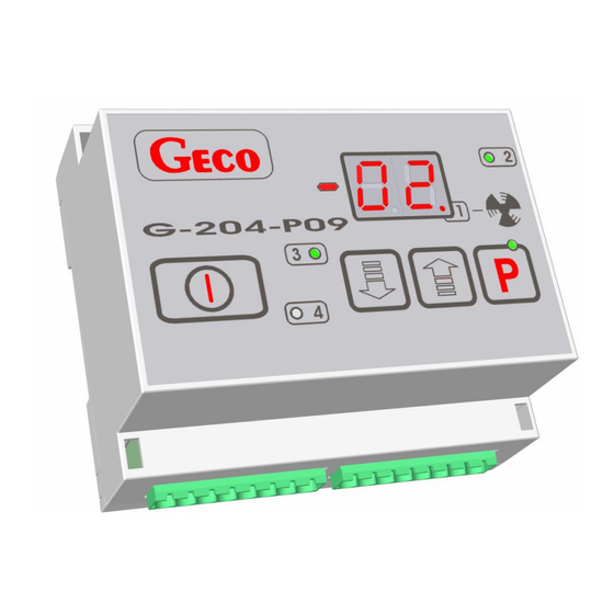
G-204-P09
VERSION FOR REFRIGERATION EQUIPMENT
For programme version 02
We strongly request that you carefully study the instructions before connecting and
commissioning any of our devices.
If you have any problems with the operation and handling of your device, please
refer to the FAQ section on our website.
www.geco.pl.
Advertisement
Table of Contents

Related Manuals for Geco G-204-P09


Summary of Contents for Geco G-204-P09
- Page 1 SERVICE MANUAL FOR THE CONTROLLER G-204-P09 VERSION FOR REFRIGERATION EQUIPMENT For programme version 02 We strongly request that you carefully study the instructions before connecting and commissioning any of our devices. If you have any problems with the operation and handling of your device, please refer to the FAQ section on our website.
-
Page 2: Table Of Contents
METHOD OF OPERATION ....................... 5 VII. PROGRAMMING OF SYSTEM PARAMETERS ................8 NOTES ON SBR PROGRAMMING......................8 VIII. OPERATION OF THE G-204-P09 FOR THE USER ..............10 PROBLEMS AND THEIR RESOLUTION ..................11 RETURNS FOR REPAIR ........................11 CONNECTION BLOCK DIAGRAM ....................12... -
Page 3: General Characteristics
G- 2 04 – P 09 K 0 X – M XXX4 X0 Model designation: Position: 1 2 3 4 5 6 7 8 1- "Geco" thermostat. 2- For refrigeration applications. 3- Housing type: 02 -mini panel, 03-large panel, 04-control in a module, 4- Beginning of panel (keyboard) markings. -
Page 4: Method Of Ordering
P3 – Universal 750W P4 – Uniwersalny 750W Attention !!! - The currents shown in the table are the currents consumed by the individual devices during normal operation and already take into account the inrush currents of these devices !!! - The total current drawn by the appliances at any one time must not exceed 10A !!! III. -
Page 5: Method Of Operation
It is not recommended to extend the sensor cable beyond 20 m. THE WAY OF CONNECTING THE SENSOR CABLES TO THE TERMINALS OF THE EXECUTIVE MODULE SENSORS IS ARBITRARY!!! (analogous to the way of inserting a plug into a ~230V contact) for cable extensions we propose to use cable type OMY 2x0.5 mm The connection of the cables in the case of extensions should be made very carefully by soldering each pair of wires and placing heat shrink sleeves over them. - Page 6 1. Evaporator blowdown The thermostat works in the opposite way to the condenser, i.e. an increase in pressure/temperature causes a decrease in blowdown. Blow czas Temperature Parameter Parameter ‘d0’or ‘d2’ or pressure ‘d1’ or ‘d3’ 2. Method of blowing A maximum of 4 fans can be connected to the thermostat, a minimum of 1. The parameters 'r1', 'r2', 'r3' are used to determine which relay the fans are connected to.
- Page 7 4. Alarms Compressor head overheating alarm If parameter 'r5' is set to 1, the compressor head overtemperature alarm is allowed. The parameter 'd7' sets the temperature above which the alarm will occur. The alarm is signalled by the display 'A4'. Temperature sensor failure alarms A failure of sensor 3 (condenser) is signalled by the display 'A1'.
-
Page 8: Programming Of System Parameters
The measured pressure can be calculated from the formula: VII. PROGRAMMING OF SYSTEM PARAMETERS After commissioning and checking the correct operation of the device (the factory default settings are entered), we proceed to enter the system parameters of the G-204. To do that, turn off the device using the button . - Page 9 2. Once the unit has been programmed and put into operation, check the operation of the unit and once again check that the system parameters have been set correctly. 3. It is absolutely forbidden to pass on to the end user the service manual or information on how to program the SBR system parameters.
-
Page 10: Viii. Operation Of The G-204-P09 For The User
0- stops the fan 1- Does not stop the fan VIII. OPERATION OF THE G-204-P09 FOR THE USER 1. When the unit is plugged in, two dots will light up on the display for one second then the unit's programme version and dots for another second. Two horizontal dashes will then light up on the central segments of the display to indicate the "live"... -
Page 11: Problems And Their Resolution
P.P.U.H. 'Geco' Sp. z o. o. shall not be liable for any loss or damage resulting from the fact that the manufacturer of the cooling appliance or its service... -
Page 12: Connection Block Diagram
CONNECTION BLOCK DIAGRAM... - Page 13 page 13...
- Page 14 P.P.U.H. „Geco” Sp. z o. o. 30-134 Kraków ul. Zarzecze 112 A Polska tel. 012 6369811, 6361290 fax. 012 6362002 http://www.geco.pl...
- Page 15 Strona umyślnie pozostawiona pusta page 15...
Need help?
Do you have a question about the G-204-P09 and is the answer not in the manual?
Questions and answers