Table of Contents
Advertisement
Quick Links
Advertisement
Table of Contents

Related Manuals for Geco GC209


Summary of Contents for Geco GC209
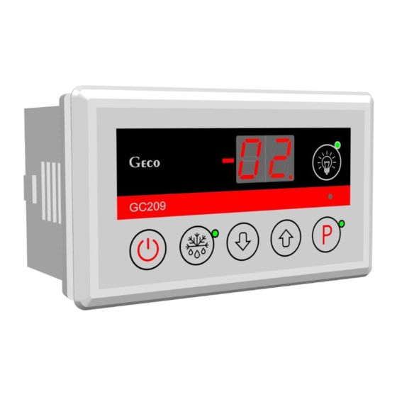
- Page 1 INSTALLATION, OPERATING AND MAINTENANCE MANUAL GC209 COOLING APPLIANCES CONTROLLER For software version 01 Please, read the manual very carefully before connecting and starting any of our devices. In case of doubt please contact our company between 8am and 4pm.
-
Page 2: Table Of Contents
Contents: GENERAL FEATURES ..............................3 MARKING AND SPECIFICATIONS ............................3 III. HOW TO ORDER ................................4 GC209 ASSEMBLY AND CONNECTION ..........................4 SENSOR MOUNTING RULES ..............................5 MODE OF OPERATION ................................. 6 A – G ENERAL INFORMATION ........................................1. Start after power on ................................ 6 2. -
Page 3: General Features
It also has a button to defrost the evaporator manually. GC209 has offers a choice of operating modes with one or two temperature sensors and has two relay outputs enabling direct connection of devices operating at 230V with the load capacity of the outputs in accordance with Table 1. -
Page 4: How To Order
1. Cut a hole measuring 57x109mm in the designated place in the device. 2. Any metal elements through which the GC209 or its cables are passed should be filed down or otherwise secured. It is not permitted to mount the GC209 allowing the direct impact of water on it (e.g. water condensing on the lower cover of the display case), touching the evaporator drain pipe, etc. -
Page 5: Sensor Mounting Rules
THE SAME CONDITION APPLIES TO ANY OTHER REPAIRS!!! 7. If heaters are used, their power must be selected so that in the event of failure of the GC209 or external contactor and switching them on permanently, there is no possibility of fire or destruction of the device. If high-power heaters are used, it is absolutely necessary to use a safety thermostat on the evaporator. -
Page 6: Mode Of Operation
- THE WAY OF CONNECTING THE SENSOR CABLES TO THE SENSOR TERMINALS OF THE ACTUATOR MODULE IS FREE!!! (similar to the method of inserting the plug into the ~230V socket) - to extend the cables, we suggest using an OMY 2x0.5mm cable - connection of the cables in the case of extensions should be done very carefully, each of the pairs of wires is soldered and heat-shrinkable sleeves are put on them. -
Page 7: Temperature Setting Programming
30-second condition has been exceeded. This is to protect the compressor from unnecessary activation, for example, caused by putting goods in, draughts, etc. Once the compressor has been turned off for the time set by parameter 'c2', the GC209 will prevent the compressor from turning back on. -
Page 8: Overheating Alarm - A4
If the defrosting function is active, and parameter r2 = 0 and the temperature on the evaporator is lower than the 'd2’ parameter setting, the GC209 activates defrosting and when the 'd2’ temperature setting is reached, the Controller enters the defrosting exit procedure (this condition is indicated by flashing of the green diode button) consisting of a single dripping phase –... -
Page 9: C - Hysteresis
3. After switching off 'dF' and the end of defrosting, the display will show the temperature stored just before the start of defrosting for the time specified in the 'c7' parameter – this is to prevent complaints due to “rapid temperature jumps in the device”. -
Page 10: Diagrams For Connecting Individual Assemblies Of The Device
VII. ON/OFF DIAGRAMS FOR INDIVIDUAL ASSEMBLIES OF THE APPLIANCE A thick line means switching on, and a dashed line means switching off individual devices. The “Downtime” field means switching off, and “Work” – switching on of the compressor due to exceeding the programmed temperature, of course, taking into account the value of the programmed hysteresis, parameter 'd3'. -
Page 11: Setting The System Parameters
VIII. SETTING THE SYSTEM PARAMETERS Once the device is started and checked for proper operation (default settings are factory set) you can begin to enter the system parameters of the GC209. To do this, turn off the device with the button (two horizontal lines will appear on the display). - Page 12 00 – NTC 2.2k 01 – NTC 10k Device connected to the second relay: 00 (for 00 – lighting GC209.02 01 – fan operating together with the compressor version) 02 – fan operating continuously 01 (for 03 – evaporator heater GC209.01...
-
Page 13: Troubleshooting
1. The display does - presence of 230V voltage at the power supply terminals L and N not light up even though the GC209 is connected to the mains - presence of 230V voltage on terminals P2 and N – If present, check the 2. -
Page 14: Returning For Repair
- amount of gas, fans, evaporator heater, evaporator drain hose RETURNING FOR REPAIR PPUH GECO reserves the right to refuse to accept the device for free repair if the seals are found to be broken!!! P.P.U.H. Geco Sp. z o.o. is not liable for losses and damage... -
Page 15: Method Of Connecting Devices To The Controller
VIEW FROM ABOVE Power supply EVAPORATOR sensor CHAMBER sensor FRONT VIEW Fig. 3 Diagram for connecting devices and sensors to the regulator model GC209.01, which does not have a button to operate the lighting. Page 15 2nd edition AS FROM 01.12.2017... - Page 16 VIEW FROM ABOVE Power supply EVAPORATOR sensor CHAMBER sensor FRONT VIEW Fig. 4 Diagram for connecting devices and sensors to the regulator model GC209.02, which is additionally equipped with a lighting control button. Page 16 2nd edition AS FROM 01.12.2017...
-
Page 17: Information On Marking And Collecting Waste Electrical And Electronic Equipment
XII. INFORMATION REGARDING MARKING AND COLLECTION OF WASTE ELECTRIC AND ELECTRONIC EQUIPMENT ATTENTION! The symbol placed on a product or on its packaging indicates that it is subject to selective collection of waste electric and electronic equipment. This means that the product should not be discarded with other household waste. - Page 20 P.P.U.H. Geco Sp. z o.o. Cholerzyn 376, 32-060 Liszki, Poland phone: +48 12 6369811, 6361290 fax: +48 12 6362002 http://www.geco.pl e-mail: geco@geco.pl...
Need help?
Do you have a question about the GC209 and is the answer not in the manual?
Questions and answers