Table of Contents
Advertisement
Quick Links
INSTALLATION, OPERATING AND MAINTENANCE MANUAL
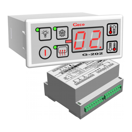
G-202-P05
COOLING APPLIANCES CONTROLLER
For software releases 01,02,03
We kindly request that you study this manual carefully PRIOR to connecting and starting
up any of our equipment. Should you have any queries or doubts, please contact us
between 8 a.m. and 4 p.m. Any comments e-mailed will be appreciated.
Advertisement
Table of Contents

Related Manuals for Geco G-202-P05


Summary of Contents for Geco G-202-P05
- Page 1 INSTALLATION, OPERATING AND MAINTENANCE MANUAL G-202-P05 COOLING APPLIANCES CONTROLLER For software releases 01,02,03 We kindly request that you study this manual carefully PRIOR to connecting and starting up any of our equipment. Should you have any queries or doubts, please contact us...
-
Page 2: Table Of Contents
Table of Contents GENERAL FEATURES ..............................3 MARKING AND SPECIFICATIONS ..........................3 III. ORDERING INFORMATION ............................. 4 DELIVERY, INSTALLATION AND CONNECTION ....................5 INSTALLATION OF SENSORS, TYPES OF COVER SHELLS ................. 6 GENERAL OPERATION PRINCIPLES ........................6 VII. ON/OFF DIAGRAMS FOR INDIVIDUAL ASSEMBLIES OF THE APPLIANCE ..........9 VIII. -
Page 3: General Features
G- 2 X –P 05K X X – M XXXX X Model designation: Items: 1 2 3 4 5 6 7 8 1- “Geco” thermostat 2- For use with cooling appliances 3- Enclosure type: 02 – minipanel, 03 – large keyboard 4- Start of designations regarding the front panel (keyboard) -
Page 4: Ordering Information
Operating voltage 230V +10% -15% Operating temperatures +5°C to +40°C Humidity 20% to 80% RH Ingress protection IP65 at the front of the control panel Table 1: Designation of relays and output loads Output Load P1 - Compressor 2HP 1500W P2 - Light 750W P3 –... -
Page 5: Delivery, Installation And Connection
DELIVERY, INSTALLATION AND CONNECTION 1. In the appropriate place within the unit cut a hole of 20x30mm in size, however if masking frame of the panel is not used the size of the hole should be 58x109mm. 2. Mount the actuator on the rail and latch it. For store equipment the SCCB actuator module MUST be fixed to the floor!!! 3. -
Page 6: Installation Of Sensors, Types Of Cover Shells
INSTALLATION OF SENSORS, TYPES OF COVER SHELLS 1. For each type of the manufactured equipment a place for securing the sensors and the SCCB settings should be determined experimentally. Absolutely do not change the fastening location nor the way the sensors are secured nor modify SCCB settings without prior carrying out new tests relating to temperature stabilization and equipment defrosting cycle !!! 2. - Page 7 by pressing the key. The display shows value of the temperature indicated by the chamber sensor. 3. If you press and hold the keys for 0.5 second, the display will start flashing and showing the temperature setting – this is the temperature programming mode; press the again to change the temperature setting.
- Page 8 Short pressing of the key turns on the LED at the key and activates the window heater or fan. After the time set in ‘d4’ the window demisting is automatically deactivated. If the parameter ‘r6’ is set to 3, then the window temperature is also stabilised. Another short press turns off the LED and the window heater/fan.
-
Page 9: On/Off Diagrams For Individual Assemblies Of The Appliance
This is especially important for the “positive temperature” appliances that must always operate at temperatures above 0°C. As a manufacturer of a cooling appliance, in this case a cooling counter (positive temperatures), we require that the device enables operation only within the range of temperatures that do not exceed the below specified values: Switching off at min. -
Page 10: Setting The System Parameters
t=c3 KOMPRESOR WENTYLATOR Postój Praca ROZMRAŻANIE WYJŚCIE Z ROZMRAŻANIA Praca Postój ‘r1’=03, evaporator heater t=c3 KOMPRESOR GRZAŁKA Postój Praca ROZMRAŻANIE WYJŚCIE Z ROZMRAŻANIA Praca Postój ‘r1’=04, tray heater t=c3 KOMPRESOR GRZAŁKA TACKI Postój Praca ROZMRAŻANIE WYJŚCIE Z ROZMRAŻANIA Praca Postój Kompresor Compressor Wentylator... - Page 11 Table 2: Designation of parameters Parame Description Min. Max. Step Factory setting Setting of the defrosting interval. Note !!! If you set this to “0”, there will be no automatic defrosting, only the manual!!! If you set this to “-01”, there will be no defrosting at all, neither automatic nor manual!!! Maximum defrosting time, if the evaporator does not reach 1min...
-
Page 12: G-202 Operation - User Instructions
02 – door opening sensor exists, open at open door 03 – temperature sensor at window Lighting activation methods: 01 – light controlled only by the door sensor 02 – light controlled only by the keyboard 03 – light controlled by both the door sensor and the keyboard Time elapsed after door opening until alarm activation. -
Page 13: Troubleshooting
TROUBLESHOOTING Symptoms Checks 1. The display is off Check: even if G-202 is - if 220V voltage is present on the power supply terminals L and N connected to the - correct connection of the actuator to the control panel power supply - remove and reinsert the ribbon sockets - connect another ribbon... -
Page 14: Returning For Repair
- if the type of thermostat (output description label) is correct for your device - if the control panel, actuator module or ribbon cable connectors were exposed to water or other liquid - if the control panel, module or ribbon cable connectors are exposed to moisture or sudden changes of temperature - correct connection of the actuator module with the control panel - replace the ribbon cable... -
Page 15: Software Release Changes
PPUH ‘GECO’ reserves the right to refuse a free repair of the unit, if there is no form, the form is not filled in completely or the seals are broken !!! P.P.U.H. ‘Geco’ Sp. z o. o. is not responsible for loses and damages resulting... -
Page 16: Block Diagram, Actuator Module View, And Execution Of The Ribbon Cable Connecting The Control Panel And The Actuator Module
XIV. BLOCK DIAGRAM, ACTUATOR MODULE VIEW, AND EXECUTION OF THE RIBBON CABLE CONNECTING THE CONTROL PANEL AND THE ACTUATOR MODULE Page 16 Revision I FROM 2012-09-20...
Need help?
Do you have a question about the G-202-P05 and is the answer not in the manual?
Questions and answers